Viewfinder display apparatus

a display apparatus and viewfinder technology, applied in the direction of instruments, focusing aids, camera body details, etc., can solve the problems of affecting the display in the viewfinder field in photographing in the dark, the efficiency of the optical waveguide is considerably poor, and the size and cost of the camera increase to deteriorate the productivity, so as to improve the productivity, reduce the cost and size, and improve the effect of productivity

Inactive Publication Date: 2005-07-19
CANON KK
View PDF9 Cites 6 Cited by
  • Summary
  • Abstract
  • Description
  • Claims
  • Application Information

AI Technical Summary

Benefits of technology

[0013]It is an object of the present invention to provide a viewfinder display apparatus and a camera which can improve productivity by reducing cost and size and making adjustment of illumination light unnecessary and which can realize superimpose having good visibility without giving uncomfortable feeling to a photographer.

Problems solved by technology

H05 (1993)-333259, an optical path extending from an illumination unit to a focusing screen is so long that a flux of light from the illumination unit is repeatedly refracted and reflected by a projection lens, a main mirror, or the like many times. Furthermore, since the main mirror is constituted by a half mirror, optical waveguide efficiency is considerably poor.
For this reason, the camera increases in size and cost to deteriorate the productivity.
On the other hand, when a focal point detection frame is entirely illuminated with LED light, although bright-light shooting can be performed without any problem, a section gleaming with the LED light adversely affects the display in the viewfinder field in photographing in the dark.
For this reason, a photographer who looks into the viewfinder may bothersomely see the display in the viewfinder.
However, since the illumination unit is arranged in the frontal region of the pentaprism, it is difficult to arrange a built-in flashlight-emitting unit in the frontal region of the pentaprism.
For example, when the display body on the focusing screen is formed in the shape of two lines, a cross, or the like, the observer is hard to see the object image depending on the shape of the display body.
However, since the position of the focusing point display section is different from an actual focusing point displayed in the viewfinder field, the visibility of the focusing point is not up much.

Method used


Image

  • Viewfinder display apparatus
  • Viewfinder display apparatus
  • Viewfinder display apparatus

Examples


first embodiment

[0033](First Embodiment)

[0034]A camera according to the first embodiment of the present invention will be described below with reference to the accompanying drawings and the like.

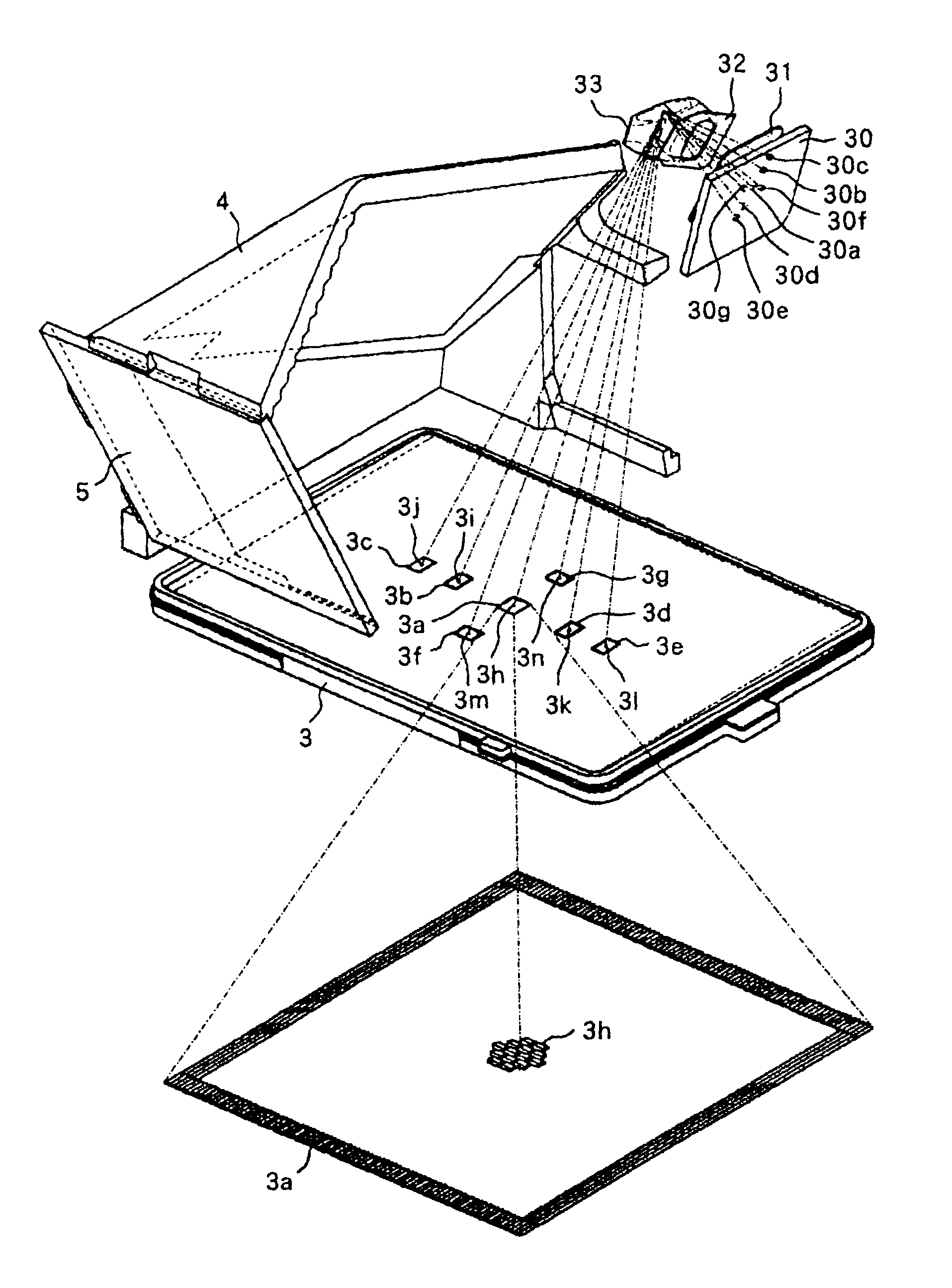
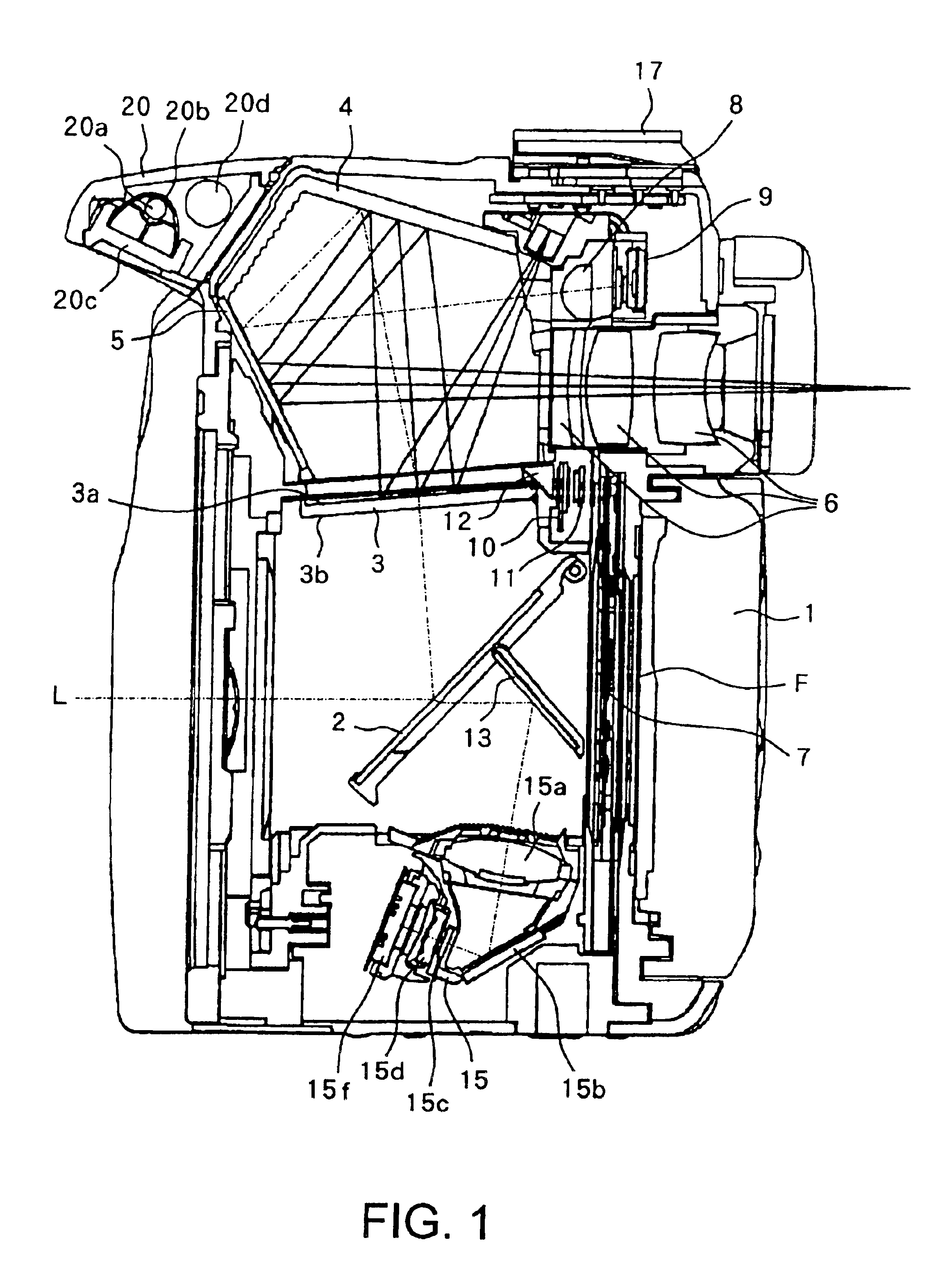
[0035]FIG. 1 is a longitudinal cross-sectional view of a camera according to this embodiment. Object light L transmitting through a photographing optical system (image-forming optical system) (not shown) is reflected by a main mirror (half mirror) 2 and then guided to a viewfinder optical system when the main mirror 2 is at an observing position (mirror-down position) as shown in FIG. 1. On the other hand, when the main mirror 2 is retreated from a photographing optical path, the object light L transmits through a focal plane shutter 7 and then forms an image on a film F. An image-pickup element such as CCD may be used instead of film.

[0036]A focusing screen 3 is arranged on a planned image-forming surface of the photographing optical system, and has an upper surface which is constituted by a mat surface 3a...

second embodiment

[0080](Second Embodiment)

[0081]A viewfinder display apparatus according to the second embodiment of the present invention will be described below.

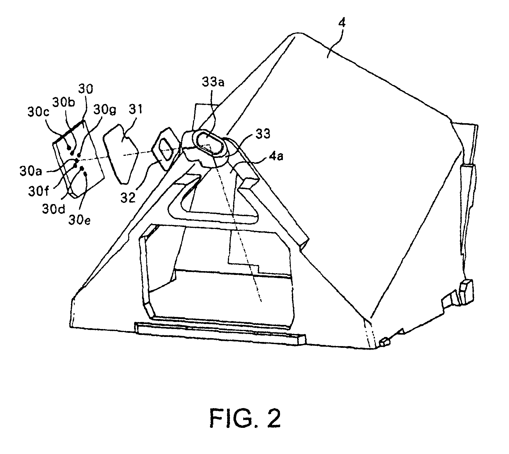
[0082]FIG. 8(A) shows a manner of actually illuminating the focal point detection frames on the focusing screen 40 with illumination light from an LED 39 for superimpose illumination in the viewfinder display apparatus according to this embodiment. In FIG. 8(A), a hollow penta mirror 4 and a third reflecting mirror 5 are shown as cross sections obtained by cutting these mirrors at their centers, respectively. FIG. 8(B) shows a central focal point detection frame 40a formed at the center of the focusing screen 40 as an enlarged view.

[0083]In FIG. 8(A), the LED-C_39a illuminates the neighborhood of the central focal point detection frame 40a. Similarly, the LED-L1_39b illuminates the neighborhood of the left middle focal point detection frame 40b, the LED-L2_39c illuminates the neighborhood of the left focal point detection frame 40c, the LE...


PUM


Abstract

A viewfinder display apparatus which can realize superimpose having good visibility without giving uncomfortable feeling to a photographer is disclosed. The viewfinder display apparatus includes an eyepiece lens unit, an a member on which illumination unit which irradiates illumination light, and a plurality of region display sections arranged in a viewfinder optical path respectively to correspond to the focus detection regions. Each of the region display sections includes an outer frame which partially transmits light from an object to display edges of the focus detection regions in the viewfinder field and reflecting region in which reflecting surface which reflects illumination light from the illumination unit to guide the reflected light to the eyepiece lens unit are formed.

Description

BACKGROUND OF THE INVENTION[0001]1. Field of the Invention[0002]The present invention relates to a viewfinder display apparatus having a superimpose display function which displays a focus detection region selected from a plurality of focus detection regions set in a viewfinder field.[0003]2. Description of the Related Art[0004]A conventional camera having a superimpose display function which is proposed in Japanese Patent Application Laid-Open No. H01 (1989)-277225 or Japanese Patent Application Laid-Open No. H05 (1993)-333259 is known. In such a conventional camera, a flux of light emitted from an illumination unit arranged in front of a pentaprism is reflected by a quick return mirror constituted by a half mirror through a projection lens to illuminate a plurality of display units arranged on a focusing screen.[0005]In a observing apparatus proposed in Japanese Patent Application Laid-Open No. H04 (1992)-278931, an illumination unit is arranged in a frontal region of a pentaprism...

Claims


Application Information

Patent Timeline
Patent Type & Authority Patents(United States)
IPC IPC(8): G03B17/20
CPCG03B17/20
Inventor HARAGUCHI, SHOSUKESAKURAI, HIROSHIHONDA, TAKANORI
Owner CANON KK
Why Eureka
Try Eureka