Method for water control

a technology of water control and water supply, applied in the field of water control, can solve the problems of increasing the amount of water produced from the well, affecting the quality of water supply, and requiring remedial measures to reduce the water/hydrocarbon production ratio, and achieve the effect of low viscosity of the composition

Inactive Publication Date: 2005-07-26
SCHLUMBERGER TECH CORP
View PDF19 Cites 33 Cited by
  • Summary
  • Abstract
  • Description
  • Claims
  • Application Information

AI Technical Summary

Benefits of technology

[0019]In a preferred variant of the invention, the surfactants are selected from a class of surfactants known in the art as viscoelastic surfactants (VES). In a variant of this embodiment, a delaying agent is added to the viscoelastic surfactants so as to delay the gelation of the composition. The structure or gel formed by the viscoelastic surfactants can be strengthened by adding a polymerization agent to the composition. The polymerization agent initiates a, preferably in situ, polymerization of the VES. In a further step, the strength of the structure or gel is enhanced through a cross-linking agent that links the polymerized viscoelastic surfactants.
[0022]Some of the advantages in the use of hydrophobically modified polymers are responsiveness to hydrocarbons resulting in a reduction in the adhesive strength of structure or gels and an extreme retardation of gelation, and solubilisation of large organic cross-linking agents.
[0026]The advantage of the above described variants of the invention is that the gel strength development over time of the compositions can be controlled such that during an injection phase the viscosity of the composition is low. After injection, i.e., after the shear forces cease, the composition will develop rapidly an intermediate gel strength based on physical interactions between molecules of the compositions. Where in contact with hydrocarbons the gel destabilizes and can be washed out during subsequent production. The remaining gel is strengthened by a chemical cross-linking of irreversible nature and, hence, can block water-bearing zones permanently.

Problems solved by technology

In these instances, the amount of water produced from the well tends to increase over time with a concomitant reduction of hydrocarbon production.
Frequently, the production of water becomes so profuse that remedial measures have to be taken to decrease the water / hydrocarbon production ratio.
However, the open production interval formed may inadvertently communicate with a water-bearing zone which is completed in the same wellbore.

Method used


Image

  • Method for water control
  • Method for water control
  • Method for water control

Examples


Embodiment Construction

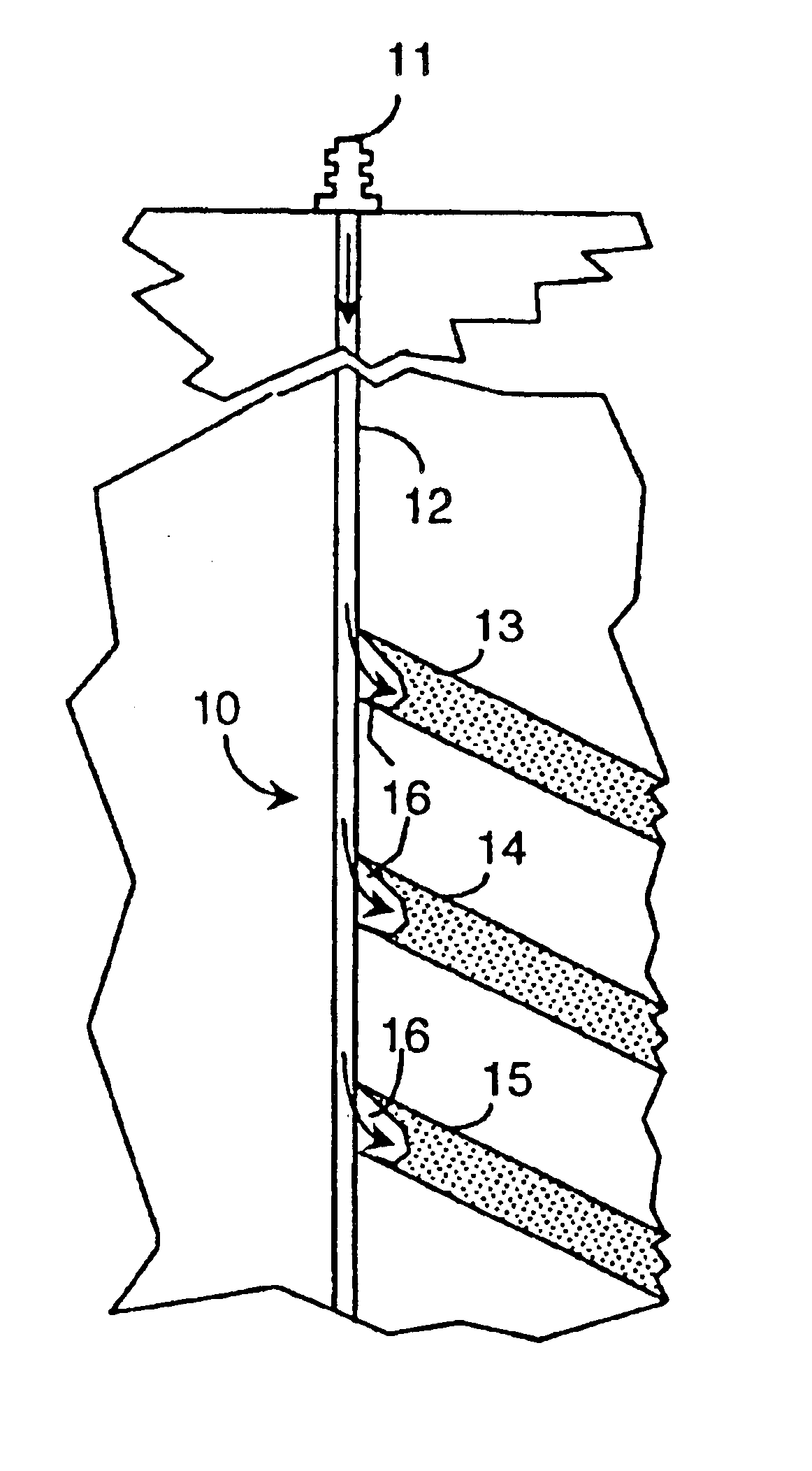
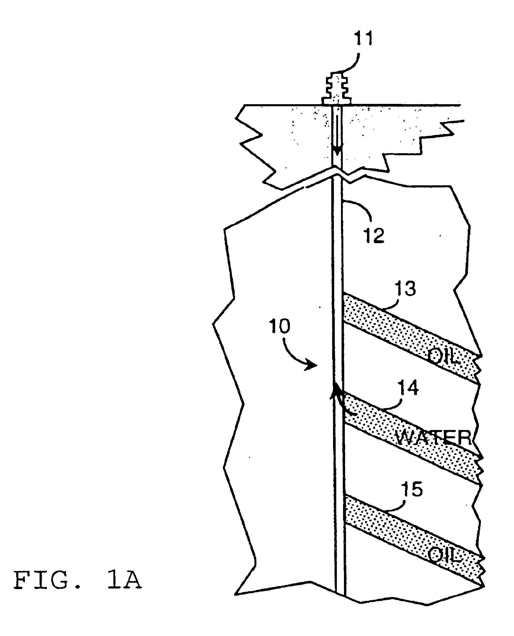
[0031]The process is described in more detail for the case of water entry through one or more zones in a multi-layered completion where the remaining layers are producing water-free oil as illustrated in FIG. 1.

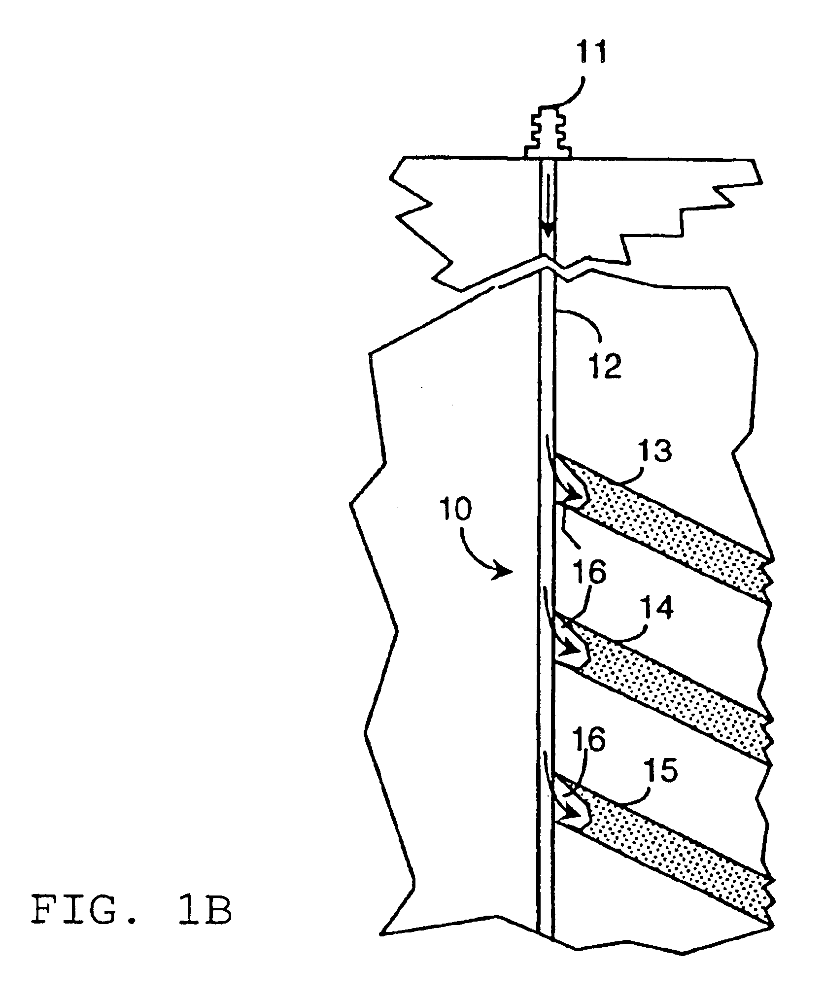
[0032]The first schematic drawing (FIG. 1A) shows a producing well 10 including wellhead 11 and wellbore 12. It is assumed that three permeable layers 13, 14, 15 have been completed with a water breakthrough in layer 14. The treatment fluid 16 is pumped from surface without mechanical isolation (packers) and invades all open zones (FIG. 1B). The treatment fluid provides a reversible, oil-sensitive structure in each layer. Such structures can be formed using compositions consisting of surfactants or hydrophobically modified polymers or mixtures thereof in combination with an agent controlling the association of the species in solution as are described in more detail below.

[0033]The well is then returned to production. The gel structure is broken by contact with oil and the tre...


PUM

PropertyMeasurementUnit
timeaaaaaaaaaa
timeaaaaaaaaaa
timeaaaaaaaaaa

Abstract

A method to reduce water influx into a producing well is described comprising the steps of pumping a chemical composition into a production interval and into surrounding formation; said composition being capable of forming, firstly, a physically stabilized structure and, secondly, a chemically stabilized structure, wherein said physically stabilized structure being dissolvable by hydrocarbon containing fluids; letting said composition form said physically stabilized structure within the formation surrounding said production interval; changing pressure condition in said production interval such that the fluid flow within the surrounding formation is reversed; letting thereby in some portions of the formation hydrocarbon containing fluids dissolve said physically stabilized structure and chemically stabilize said structure in the remaining portions by a cross-linking reaction. The time constants of the two stabilizing reactions are selected such that the physical stabilization is essentially completed before the pumping direction is reversed and the chemical stabilization is essentially completed after the pump-out / cleaning operation.

Description

[0001]The present invention relates to methods of reducing the water production of a hydrocarbon well drilled through subterranean formations. More particularly it relates to such methods for selectively reducing the flow of subterranean aqueous fluids into a well while maintaining its hydrocarbon production.BACKGROUND OF THE INVENTION[0002]During the life cycle of a hydrocarbon well, e.g., a well for extracting oil or natural gas from the Earth, the producing well commonly also yields water. In these instances, the amount of water produced from the well tends to increase over time with a concomitant reduction of hydrocarbon production. Frequently, the production of water becomes so profuse that remedial measures have to be taken to decrease the water / hydrocarbon production ratio. As a final consequence of the increasing water production, the well has to be abandoned.[0003]Various techniques have been developed and used for reducing the quantity of water produced from oil and / or gas...

Claims


Application Information

Patent Timeline
Patent Type & Authority Patents(United States)
IPC IPC(8): C09K8/512C09K8/50E21B43/00E21B43/32
CPCC09K8/512E21B43/32
Inventor DAVIES, STEPHEN N.JONES, TIMOTHY G. J.OLTHOFF, SILKETUSTIN, GARY J.
Owner SCHLUMBERGER TECH CORP
Why Eureka
Try Eureka