Cooling air system for small vehicle

Inactive Publication Date: 2005-07-26
YAMAHA MOTOR CO LTD
View PDF37 Cites 53 Cited by
  • Summary
  • Abstract
  • Description
  • Claims
  • Application Information

AI Technical Summary

Benefits of technology

[0009]Thus, a brake cooling system is desired in which the ducting is spaced from heat sources, such as th

Problems solved by technology

While cooling air has been supplied to a shaft drive brake system in the past, such attempts to cool the brake system have created other problems.
If the air is heated in this manner, the cooling efficiency of the cooling system is adversely affected.
In addition, depending upon the construction of the coo

Method used


Image

  • Cooling air system for small vehicle
  • Cooling air system for small vehicle
  • Cooling air system for small vehicle

Examples


Embodiment Construction

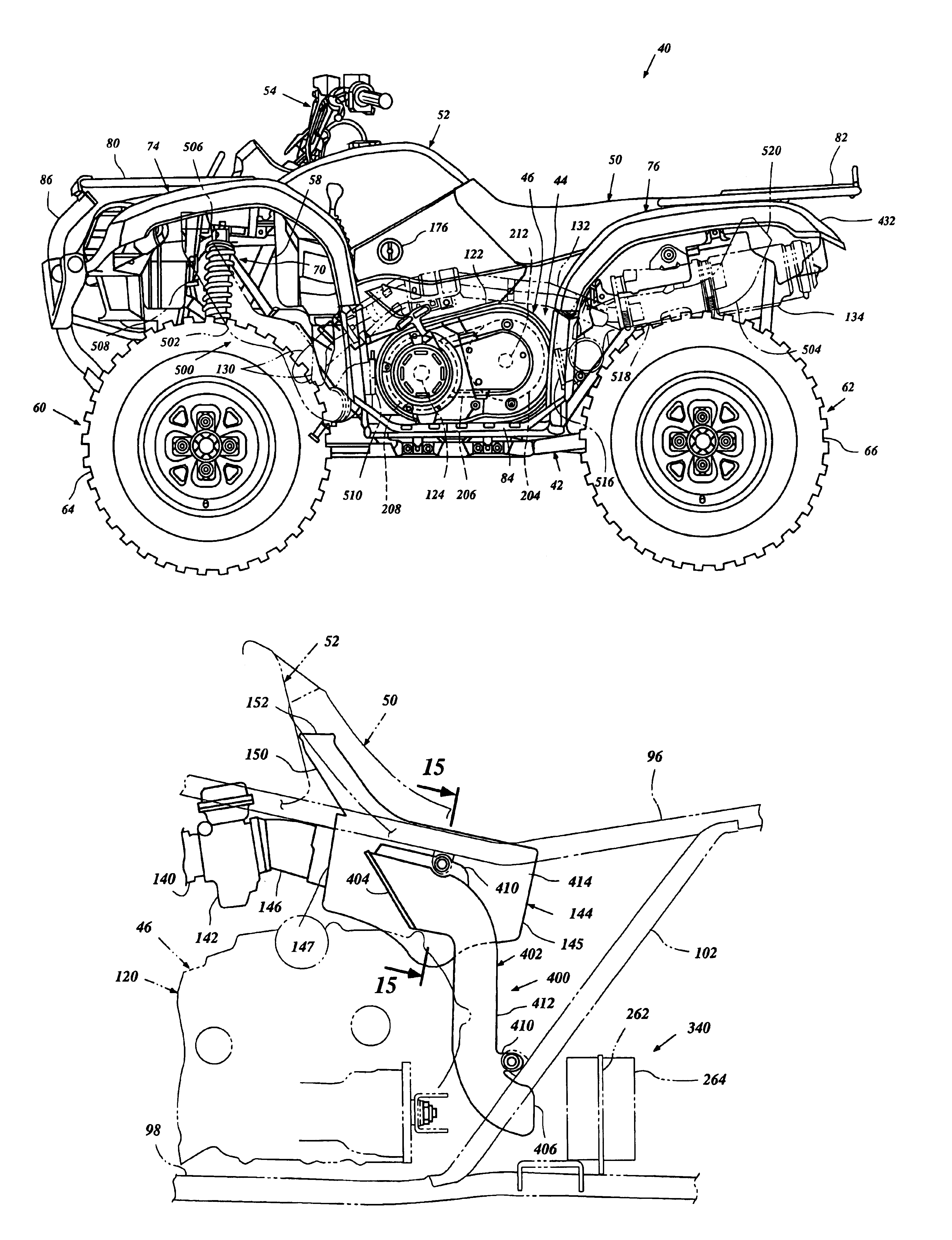
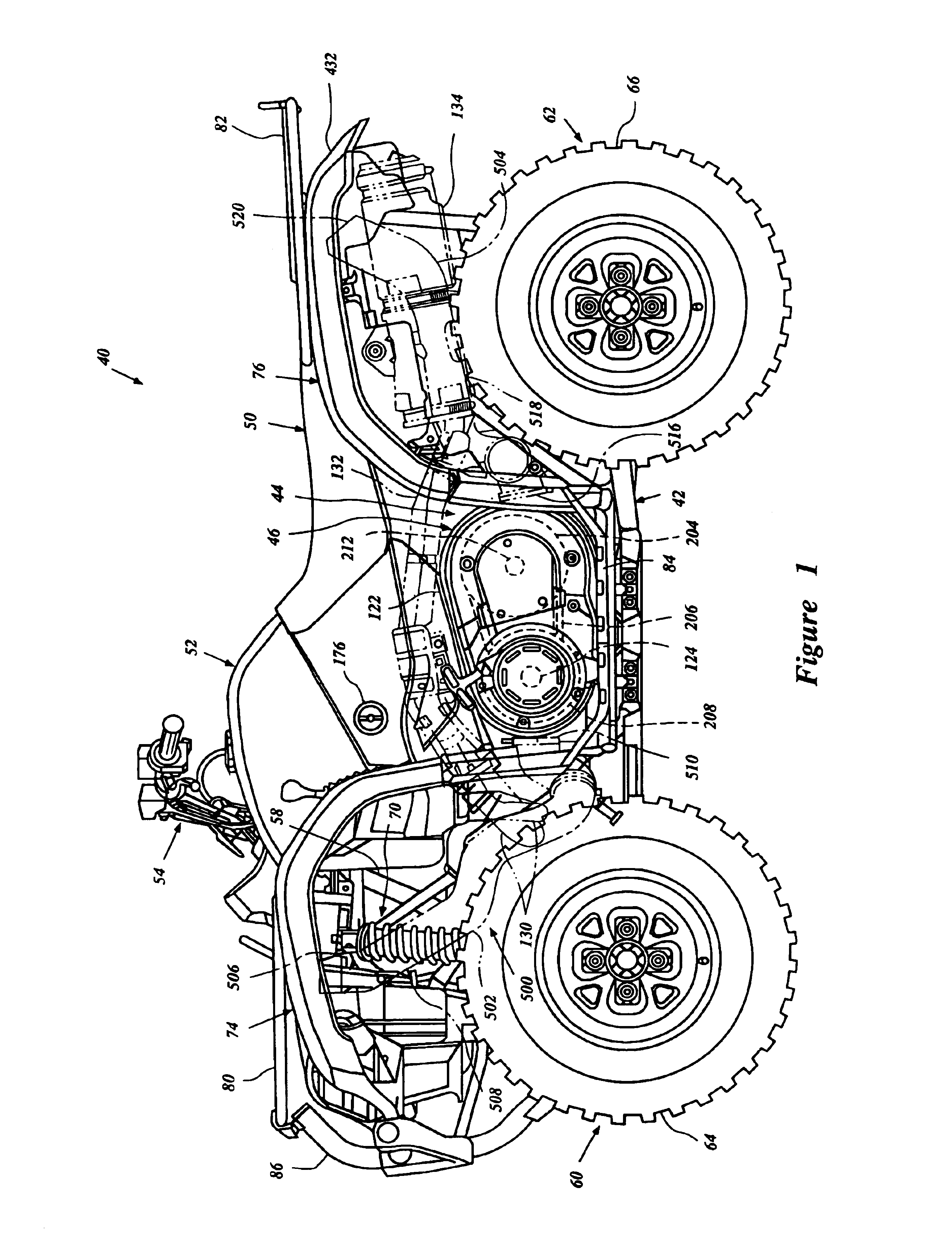
[0029]With reference now to FIG. 1, a small all terrain vehicle 40 that is arranged and configured in accordance with certain features, aspects and advantages of the present invention is shown. The vehicle comprises a frame assembly 42. The frame assembly 42 can have any suitable construction.

[0030]In the illustrated arrangement, the frame assembly 42 comprises a double cradle construction, in which the frame assembly 42 defines an engine compartment 44. An engine unit 46 is positioned within the engine compartment 44. The engine unit 46 preferably is centrally positioned within the frame assembly 42.

[0031]As is conventional in the design of smaller all terrain vehicles, a seat 50 is positioned generally above the engine unit 46. Generally, the seat 50 is a saddle-type seat, which allows an operator to sit on the seat 50 with a leg disposed to each lateral side of the seat. In some arrangements, however, the seat 50 can be configured to allow an operator to have his or her legs and ...


PUM


Abstract

A small vehicle has a frame assembly that is supported by rear wheels. An engine is supported by the frame assembly. The rear wheels are driven by the engine through a shaft drive arrangement. A brake assembly is connected to the shaft drive arrangement. An exhaust system extends away from the engine. An air cleaner is positioned along an air induction system of the engine. The air cleaner is positioned between the exhaust system and a cooling air duct that supplies cooling air to the brake assembly.

Description

PRIORITY INFORMATION[0001]This application is based on and claims priority to Japanese Patent Application No. 2001-243127, filed Aug. 10, 2001, the entire contents of which is hereby expressly incorporated by reference.BACKGROUND OF THE INVENTION[0002]1. Field of the Invention[0003]The present invention generally relates to cooling air supply systems of small vehicles. More particularly, the present invention relates to brake system cooling arrangements for small vehicles, such as an all terrain vehicles, for example.[0004]2. Description of the Related Art[0005]Small all terrain vehicles generally feature a frame assembly that supports a fuel tank and a seat. An engine is generally positioned within an engine compartment defined by the frame assembly and is located generally beneath the seat and / or fuel tank. In conventional small all terrain vehicles, the frame assembly is supported by at least one front wheel and two rear wheels. The wheels are driven by a shaft, belt or chain dri...

Claims


Application Information

Patent Timeline
IPC IPC(8): B60T1/06B62K5/00B60T1/00B60T5/00B62J99/00F16D65/847
CPCB60T1/062B60T5/00B62K5/01Y10S180/908
Inventor MATSUURA, TATSUYAISODA, TAKASHI
Owner YAMAHA MOTOR CO LTD
Why Eureka
Try Eureka