Loudspeaker diaphragm

a technology of loudspeaker and diaphragm, which is applied in the direction of transducer diaphragm, electromechanical transducer, instruments, etc., can solve the problems of increasing the height at the center portion, increasing the mass of the vibrating system of the loudspeaker, and limiting the conventional structure to slim down the diaphragm. , to achieve the effect of reproducing high-quality sound and reducing the thickness of the loudspeaker

Active Publication Date: 2005-07-26
SOVEREIGN PEAK VENTURES LLC
View PDF37 Cites 40 Cited by
  • Summary
  • Abstract
  • Description
  • Claims
  • Application Information

AI Technical Summary

Benefits of technology

[0009]Therefore, an object of the present invention is to provide a loudspeaker diaphragm capable of reducing the thickness of a loudspeaker. Another object of

Problems solved by technology

However, such a dome-like portion or a voice coil bobbin required to strengthen the center portion of the diaphragm disadvantageously increases the height at the center portion.
Therefore, there is a limit in the conventional structure to slim down the diaphragm.
Moreover, particularly in the case of streng

Method used


Image

  • Loudspeaker diaphragm
  • Loudspeaker diaphragm
  • Loudspeaker diaphragm

Examples


embodiment 1

[0039](Embodiment 1)

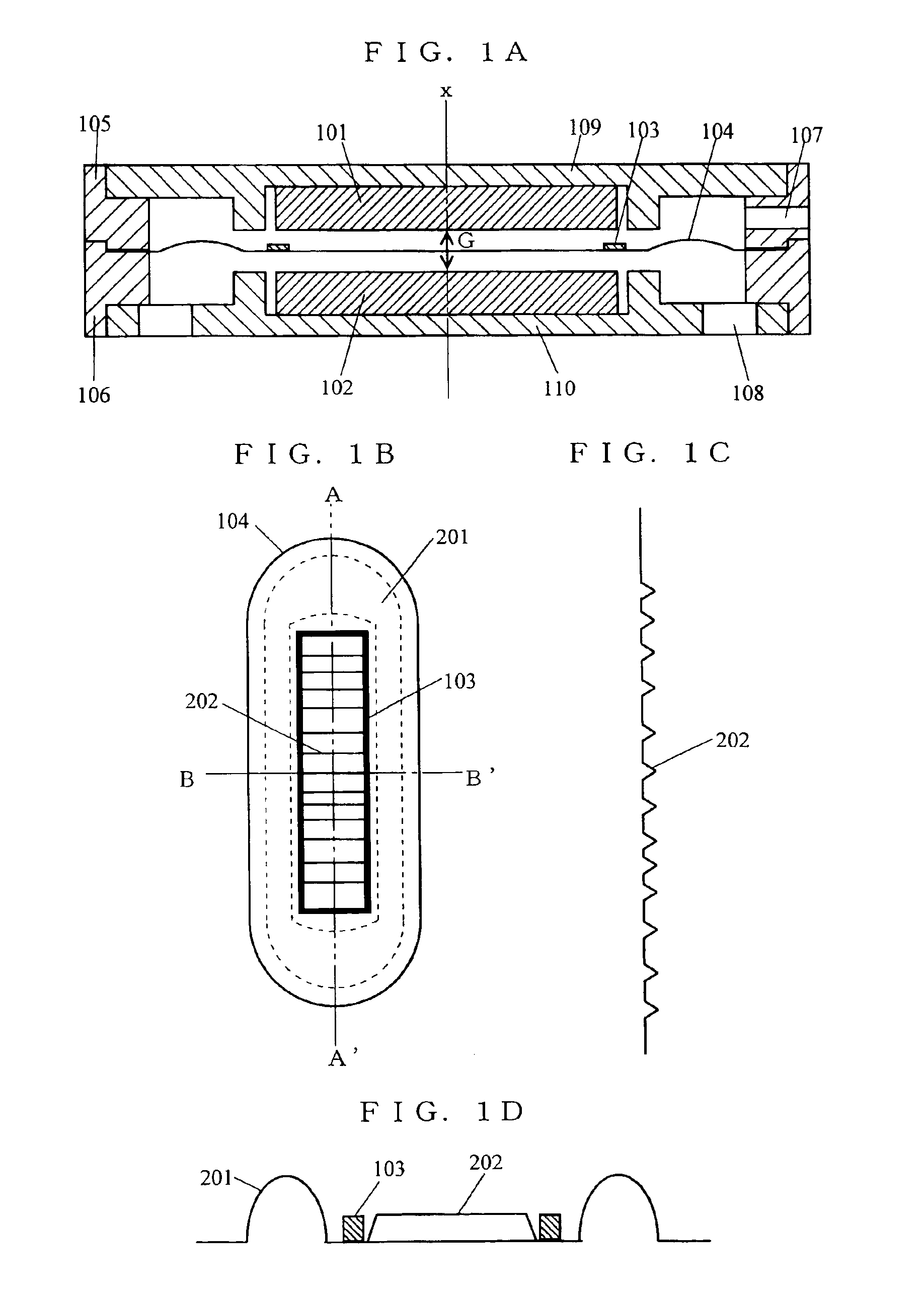
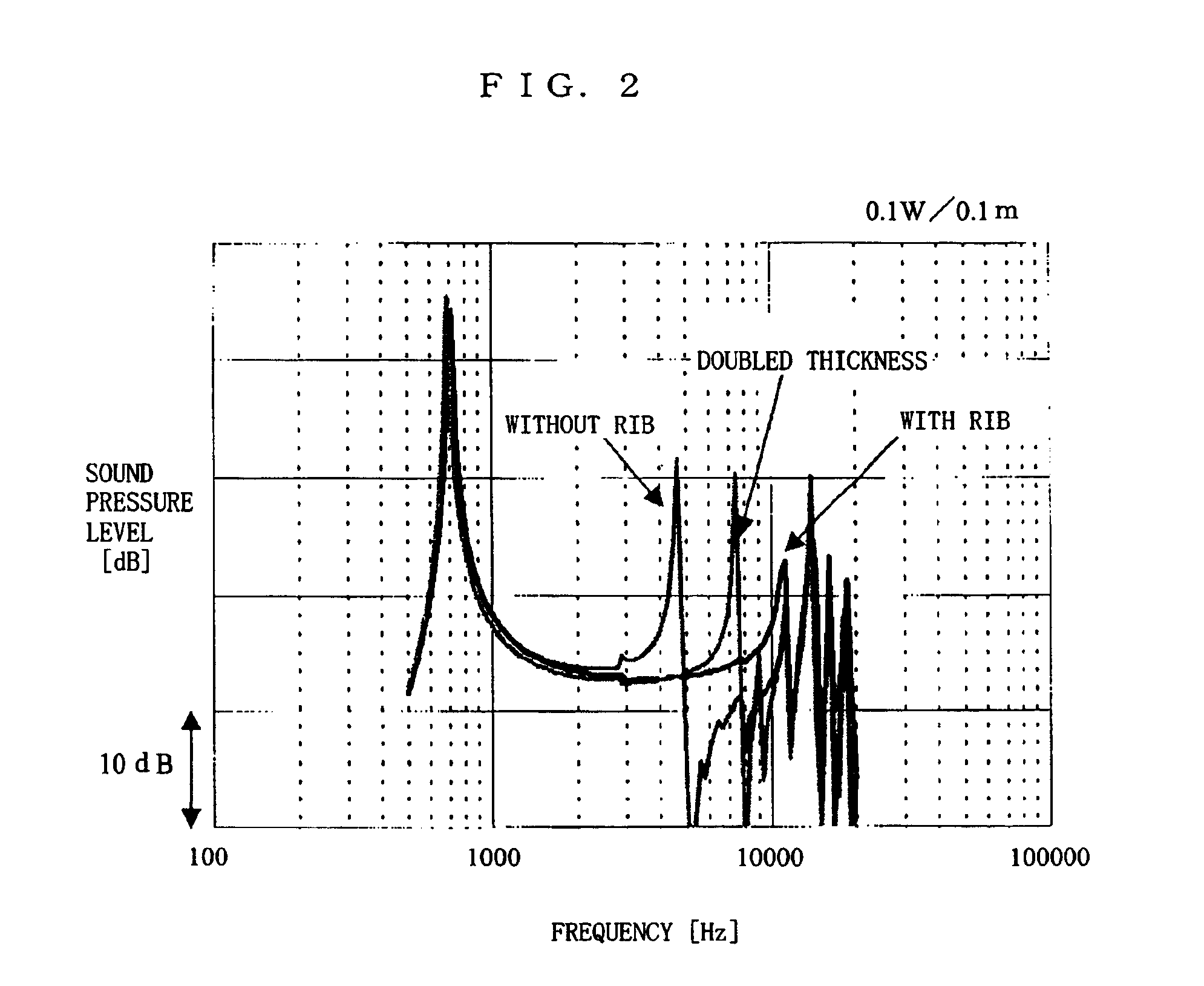
[0040]First, a loudspeaker diaphragm (hereinafter simply referred to as “diaphragm”) according to Embodiment 1 of the present invention is described below with reference to FIGS. 1A through 1D and FIG. 2. FIGS. 1A through 1D are illustrations showing the structure of the loudspeaker using the diaphragm according to Embodiment 1. FIG. 2 is a graph showing sound pressure frequency characteristics of the loudspeaker using the diaphragm according to Embodiment 1.

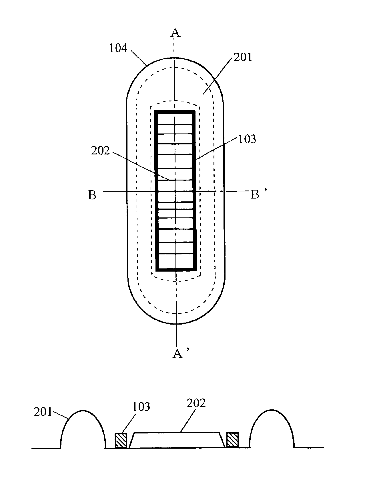
[0041]FIG. 1A is a cross section view of the loudspeaker. In FIG. 1A, the loudspeaker includes a first magnet 101, a second magnet 102, a coil 103, a diaphragm 104, a first housing 105, a second housing 106, a first yoke 109, and a second yoke 110. The first housing 105 is provided with a first air hole 107. The second yoke 110 is provided with a second air hole 108. Although not shown, the loudspeaker has an outer shape of a rectangular parallelepiped having a bottom surface shaped in a rectangle whose long ...

embodiment 2

[0059](Embodiment 2)

[0060]A diaphragm according to Embodiment 2 of the present invention is described below with reference to FIGS. 7A through 7C and FIG. 8. FIGS. 7A through 7C are illustrations showing the diaphragm according to Embodiment 2. FIG. 8 is an illustration showing vibration modes of the diaphragm according to Embodiment 2. As with Embodiment 1, the diaphragm according to Embodiment 2 is used as being connected to a loudspeaker, although not shown. Furthermore, in Embodiment 2, the components identical to those in Embodiment 1 are provided with the same reference numerals.

[0061]FIG. 7A is a top plan view of the diaphragm according to Embodiment 2. As illustrated in FIG. 7A, the diaphragm 301 is shaped so as to extend in the longitudinal direction in FIG. 7A. That is, as with the diaphragm 104, the diaphragm 301 has a shape having different lengths in the longitudinal direction and the horizontal direction.

[0062]The diaphragm 301 is different from the diaphragm 104 in th...


PUM


Abstract

A loudspeaker diaphragm affixed with a coil includes an edge portion located outside of a portion affixed with the coil and a center portion located inside of the portion affixed with the coil. The center portion is provided thereon with ribs. With these ribs, the height of the center portion can be limited to the height of the ribs. Therefore, it is possible to save a space of a loudspeaker where the loudspeaker diaphragm is placed, thereby slimming down the loudspeaker. Furthermore, with these ribs, the rigidity of the center portion can be improved without using a conventional solution of forming, for example, a dome shape on the center portion.

Description

BACKGROUND OF THE INVENTION[0001]1. Field of the Invention[0002]The present invention relates to loudspeaker diaphragms and, more specifically, to a loudspeaker diaphragm for use in a loudspeaker which is expected to be reduced in thickness.[0003]2. Description of the Background Art[0004]In recent years, electronic devices, such as cellular phones and PDAs (personal digital assistants), have been slimmed down and equipped with a larger screen, while still being expected to produce high-quality sound. Accordingly, loudspeakers incorporated in such electronic devices are similarly expected to be slimmed down and to still produce high-quality sound. To fulfill such expectations, rectangular- or oval-shaped slim loudspeakers have been suggested.[0005]FIGS. 12A and 12B are illustrations showing the structure of a conventional slim loudspeaker. FIG. 12A is a top plan view of the conventional slim loudspeaker, and FIG. 12B is a front elevational view thereof. In FIGS. 12A and 12B, the slim...

Claims


Application Information

Patent Timeline
IPC IPC(8): H04R7/12H04R7/00
CPCH04R7/14H04R9/06H04R7/12
Inventor USUKI, SAWAKOSAIKI, SHUJI
Owner SOVEREIGN PEAK VENTURES LLC
Why Eureka
Try Eureka