System and method for increasing projector amplitude resolution and correcting luminance non-uniformity

a projector and amplitude resolution technology, applied in the field of electronic imaging systems, can solve the problems of unnatural artifacts appearing in projected images, detracting substantially from the quality of projected images, and non-uniform luminance, so as to achieve the effect of improving performan

Inactive Publication Date: 2005-07-26
HEWLETT PACKARD DEV CO LP
View PDF10 Cites 52 Cited by
  • Summary
  • Abstract
  • Description
  • Claims
  • Application Information

AI Technical Summary

Benefits of technology

[0013]Briefly, the present invention recites a system and method for correcting the luminance non-uniformity and increasing the apparent amplitude resolution an image generated by a projector. The projector, which has a given number of stated levels, receives input data and projects images based on that input data. To correct luminance non-uniformity, a projector correction look-up table (LUT) is created. The LUT attenuates the displayed image such that the whole image has the same luminance as the dimmest point. Input data received by the projector is modified by the correction information contained in the LUT. In addition, the output of the projector is analyzed to identify the number of unique levels that the projector is capable of producing, which may be less than the number of stated levels. A dithering engine is utilized to further modify the corrected image data to increase the projector's apparent amplitude resolution, thereby creating the illusion that the projector has more than its unique number of levels.
[0015]To improve performance, the LUT may be converted into a one-dimensional (1-D) gain table, that specifies a gain for each projector output level, and a two-dimensional (2-D) spatial attenuation array. The level generated by the 1-D gain table and the 2-D spatial attenuation array is then provided as an input to the dithering engine. The dithering engine converts the input level to an output level based on the specified dither template. The output level is then converted to a unique projector level and utilized in generating the projected image.

Problems solved by technology

This non-uniformity in luminance detracts from the displayed image.
In addition, some projectors cause unnatural artifacts to appear in projected images.
The appearance of false contours can substantially detract from the quality of the projected image.

Method used


Image

  • System and method for increasing projector amplitude resolution and correcting luminance non-uniformity
  • System and method for increasing projector amplitude resolution and correcting luminance non-uniformity
  • System and method for increasing projector amplitude resolution and correcting luminance non-uniformity

Examples


Embodiment Construction

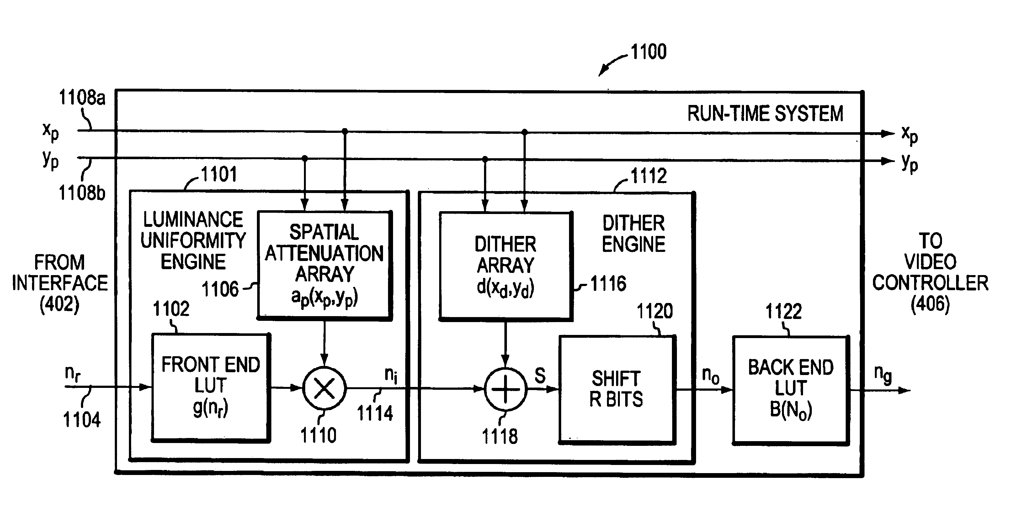
[0026]EMBODIMENT FIG. 4 is a highly schematic, partial block diagram of a digital projector 400 in accordance with the present invention. Projector 400 has an interface 402 for receiving input video data from a source, such as a personal computer (PC), a DVD player, etc. In accordance with the present invention, the projector 400 is configured to include a luminance correcting and amplitude resolution increasing (LCARI) engine 404 that receives the picture element (pixel) data from interface 402. As described herein, engine 404 modifies the received pixel data to correct for luminance non-uniformities and to increase the apparent resolution of the projector 400. Projector 400 further includes a video controller 406 that receives the “corrected” pixel data from engine 404, and performs some additional processing on that data, such as synchronization, linearization, etc. The pixel data is then sent to a light engine 408 for projecting an image to be displayed based on the pixel data r...


PUM


Abstract

A system and method corrects luminance non-uniformity and increases the apparent amplitude resolution of an image generated by a projector. The projector, which has a given number of stated levels, receives input data and projects images based on that input data. To correct luminance non-uniformity, a projector correction look-up table (LUT) is created. The LUT attenuates the displayed image such that the whole image has the same luminance as the dimmest point. Input data received by the projector is modified by correction information containing in the LUT. The projector output is analyzed to identified the number of unique levels that the projector is capable of producing, which may be less than the number of stated levels. A dithering engine modify the corrected image data to increase the projector's amplitude resolution, creating the illusion of the projector having more than the limited number of unique levels identified.

Description

BACKGROUND OF THE INVENTION[0001]1. Field of the Invention[0002]The present invention relates to electronic imaging systems and, more specifically, to correcting projected or displayed images.[0003]2. Background Information[0004]Currently, there are a wide-variety of digital image projectors commercially available. Most digital projectors include a video decoder and a light engine. The video decoder converts video data received by the projector, e.g., from the display connection of a personal computer (PC), into pixel and color data. The pixel and color data is then supplied to the light engine, which converts that data into the actual projected image. The light engine includes a lamp, optics and logic for manipulating the light in order to generate the pixels and color.[0005]There are three different types of technologies utilized by the light engines of today's projectors: Liquid Crystal Display (LCD), Digital Light Processing (DLP) and Liquid Crystal on Silicon (LCOS). An LCD lig...

Claims


Application Information

Patent Timeline
Patent Type & Authority Patents(United States)
IPC IPC(8): G03B21/00G03B21/14G06K9/40H04N5/64H04N5/74
CPCH04N5/74
Inventor ULICHNEY, ROBERT A.ARORA, HIMANSHU
Owner HEWLETT PACKARD DEV CO LP
Why Eureka
Try Eureka