Reconfigurable scanner and RFID system using the scanner

a scanner and scanner technology, applied in the field of rfid (radio frequency identification), can solve the problems of mutual interference of the antenna with the other antenna, detuning the antennas in the array, and creating unavoidable mutual inductance and electromagnetic wave interference between the antennas, etc., to achieve the effect of eliminating interferen

Inactive Publication Date: 2005-07-26
ANDERSON THEODORE R
View PDF12 Cites 63 Cited by
  • Summary
  • Abstract
  • Description
  • Claims
  • Application Information

AI Technical Summary

Benefits of technology

[0017]It is an object of the present invention to provide a scanning sensor array which eliminates interference between adjacent sensors in the array in both near-field and far-field application environments.

Problems solved by technology

A problem with all metal antennas used in a sensing array is that even when they are not active, several antennas arranged in a multiple orientation array still create unavoidable mutual inductance and electromagnetic wave interferences between antennas.
That is, even if the metal antenna sensors in an array are sequentially activated, they still cause mutual interference with other ones of the antennas.
The interferences result in detuning of the antennas in the array, so that special considerations must be made when forming arrays of metal antennas.

Method used


Image

  • Reconfigurable scanner and RFID system using the scanner
  • Reconfigurable scanner and RFID system using the scanner
  • Reconfigurable scanner and RFID system using the scanner

Examples


Embodiment Construction

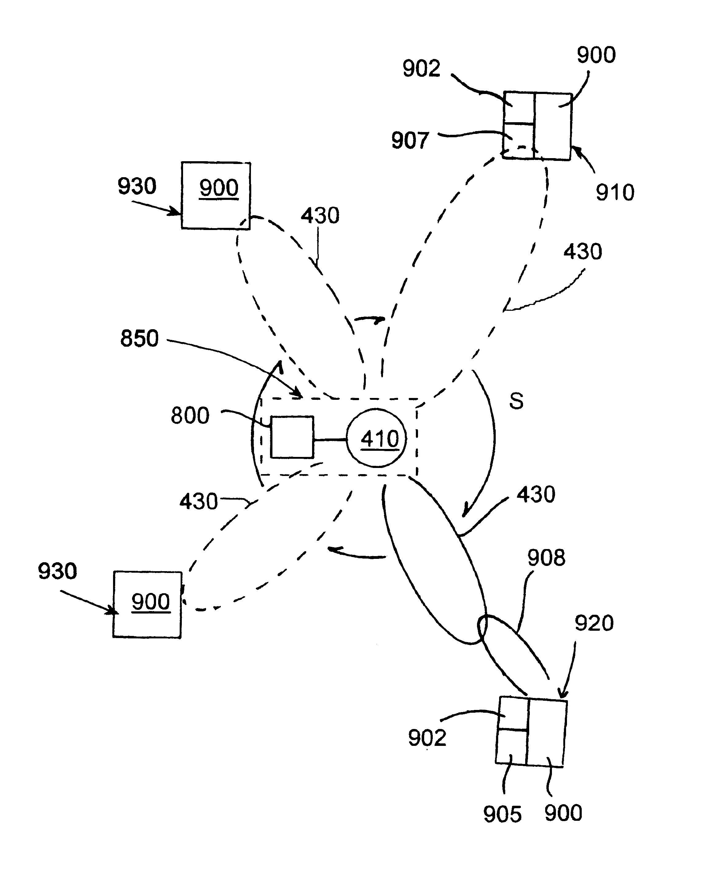
[0072]As used herein, plasma loop sensor and plasma loop reader are intended to both mean an active loop device having at least a section of plasma tube, as will be described further herein, when used in the near-field, and composed of only plasma tubes in far-field applications. The active loop device is an electro-magnetic transducer having a conductive plasma section. That is, the plasma loop reader or sensor can both generate a magnetic field or electromagnetic wave, depending on whether it is for near or far-field applications, and sense a corresponding interfering induction current or electromagnetic wave caused by a passive or active loop within range of the reader or sensor.

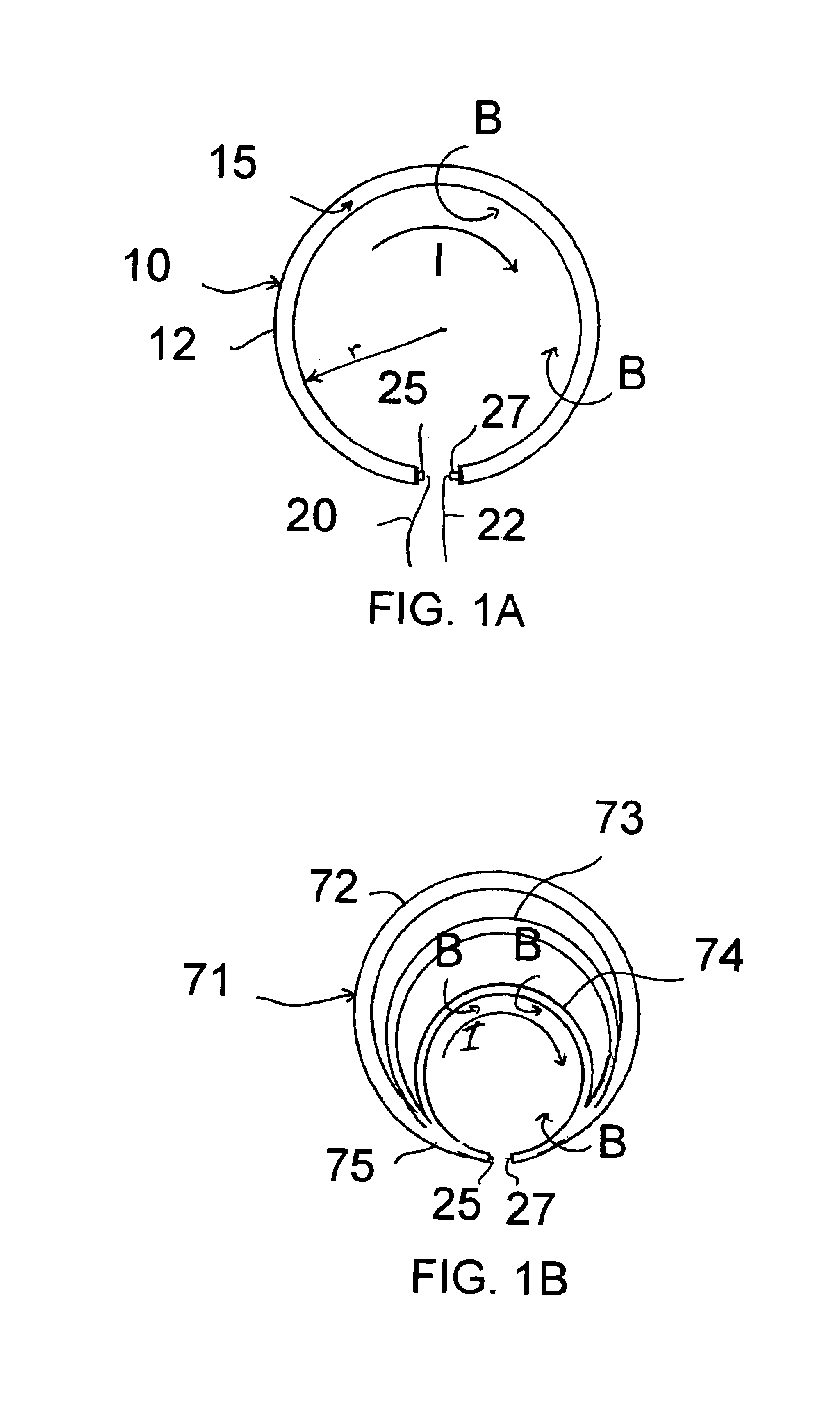
[0073]The terms plasma tube or plasma loops referring to plasma elements should not be taken as limiting on the geometric shape generally defined by the stated shape, except when the shape is essential to the function of the plasma element. Any linear dipole, traveling wave antenna, Yagi antenna, log peri...


PUM


Abstract

A scanner has plasma loop or plasma window antennas for selectively scanning for ID tags along distinct radials of the scanner. Scanner elements are made electromagnetically invisible to adjacent elements by removing power or lowering plasma densities so that the scanner elements do not interfere with its own operation. Activatable ID tags and a shipping container suitable for scanning with electromagnetic energy are also disclosed.

Description

CROSS-REFERENCE TO RELATED APPLICATION[0001]This application is a continuation-in-part of U.S. Pat. No. 6,700,544 application Ser. No. 10 / 067,715 filed Feb. 5, 2002, the entirety of which is hereby incorporated by reference. This application is also a continuation-in-part of U.S. Pat. No. 6,870,517 application Ser. No. 10 / 648,878 filed Aug. 27, 2003, the entirety of which is hereby incorporated by reference.FIELD AND BACKGROUND OF THE INVENTION[0002]The present invention relates generally to the field of RFID (radio frequency identification) and in particular to a new and useful plasma-based sensor array used to detect the presence of an interactive element resulting from interaction of antennas having variable conductive sections by magnetic induction and / or electromagnetic waves.[0003]RFID systems have gained much popularity recently as a means for wireless tracking of individual objects for a variety of purposes. For example, some retailers have proposed using unique RFID tags at...

Claims


Application Information

Patent Timeline
Patent Type & Authority Patents(United States)
IPC IPC(8): H01Q1/22H01Q1/36H01Q7/00G06FG06K7/00H01Q1/26H01Q3/46H01Q11/12H01Q21/06
CPCG06K7/0008H01Q1/22H01Q1/2216H01Q1/26H01Q1/366H01Q3/46H01Q7/00H01Q21/061
Inventor ANDERSON, THEODORE R.
Owner ANDERSON THEODORE R
Why Eureka
Try Eureka