Beam masking to reduce cyclic error in beam launcher of interferometer

a beam launcher and beam technology, applied in the field of reflection structures, can solve the problems of cyclic error, cyclic error manifesting itself, and cyclic error in general cannot be calibrated out, so as to reduce the amount of light, optimize the mask dimension, and reduce the cyclic error in the beam launcher

Inactive Publication Date: 2005-07-26
LOCKHEED MARTIN CORP
View PDF9 Cites 8 Cited by
  • Summary
  • Abstract
  • Description
  • Claims
  • Application Information

AI Technical Summary

Benefits of technology

[0021]Embodiments of the present invention are directed to reducing cyclic error in the beam launcher of an interferometer. The cyclic error can be caused by cross-talk between various optical paths, such as leakage through a polarizing beam-splitter or by stray-light reflection. Cyclic error manifests itself as an error in the measurement that leads or lags the true measurement as the measured distance changes by generally the length of one wavelength of the laser light. The cyclic error in general cannot be calibrated out as the phase of the error can change with thermal conditions. The inventors discovered another source of signal contamination that resulted from the spatially separated (e.g., co-aligned) beams diffracting into one another. Although the measurement and reference beams are spatially separated, diffraction will cause a small amount of reference beam energy to leak into the measurement beam path and / or a small amount of measurement beam energy to leak into the reference beam path, causing cyclic nonlinearity. To keep this error to less than 10 picometer (pm), the leakage should be kept below about 80 dB. One or more strategically sized and placed masks are used to reduce the amount of light that could diffract from one path into the other. Diffraction models are used to predict the cyclic error of various configuration, and to optimize mask dimension(s) for optimal performance by balancing cross-talk power with signal power to minimize the ratio of contamination to signal. As a result, the one or more masks are sized to block the diffracted contaminant signal while passing the desired measurement or reference beam.

Problems solved by technology

The cyclic error can be caused by cross-talk between various optical paths, such as leakage through a polarizing beam-splitter or by stray-light reflection.
Cyclic error manifests itself as an error in the measurement that leads or lags the true measurement as the measured distance changes by generally the length of one wavelength of the laser light.
The cyclic error in general cannot be calibrated out as the phase of the error can change with thermal conditions.
Although the measurement and reference beams are spatially separated, diffraction will cause a small amount of reference beam energy to leak into the measurement beam path and / or a small amount of measurement beam energy to leak into the reference beam path, causing cyclic nonlinearity.

Method used


Image

  • Beam masking to reduce cyclic error in beam launcher of interferometer
  • Beam masking to reduce cyclic error in beam launcher of interferometer
  • Beam masking to reduce cyclic error in beam launcher of interferometer

Examples


Embodiment Construction

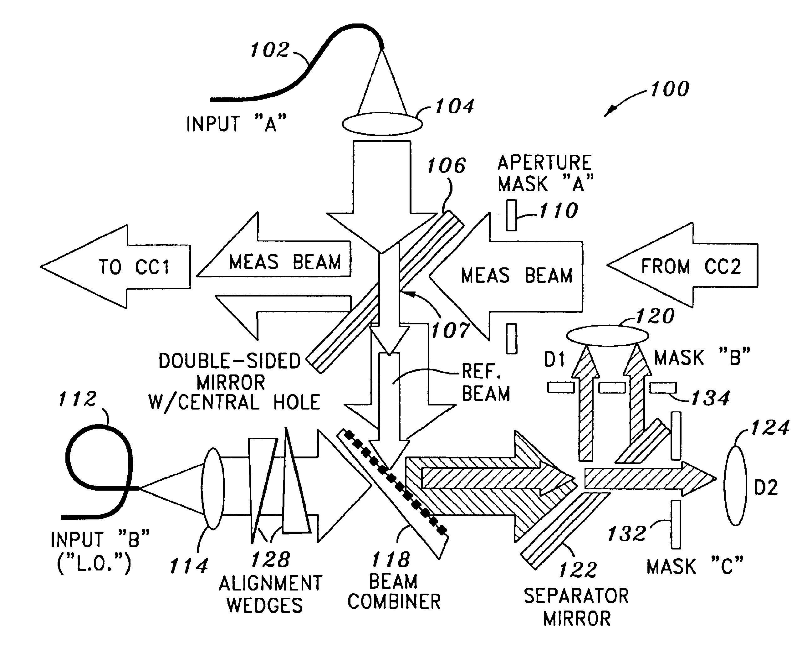
[0041]FIG. 4 shows the beam paths in a beam launcher 100 according to an embodiment of the invention. One of the laser beams (beam “A”) enters via a fiber 102 at the top of the sketch and is collimated by a collimator 104. The beam A hits a Double-sided Mirror 106 having a hole 107 and is reflected off to the left, to interrogate the retro “corner cube 1” (CC1). The launcher 100 has a “racetrack” configuration, i.e., the beam measures the distance between two retros by making a loop. In such a configuration, the beam goes to the first corner cube and hits it off-center; the reflected beam is offset and goes past the launcher to hit the second corner cube off to the right; and the beam reflected by that is offset again and now lines up with the entrance aperture mask “A”110. The beam hits the back side of the Double-sided Mirror 106 and proceeds down. The light of beam “B” (the LO beam) entering via a fiber 112 is collimated by a collimator 114 and mixed with the Measurement Beam at ...


PUM


Abstract

Embodiments of the present invention are directed to reducing cyclic error in the beam launcher of an interferometer. In one embodiment, an interferometry apparatus comprises a reference beam directed along a reference path, and a measurement beam spatially separated from the reference beam and being directed along a measurement path contacting a measurement object. The reference beam and the measurement beam have a single frequency. At least a portion of the reference beam and at least a portion of the measurement beam overlapping along a common path. One or more masks are disposed in the common path or in the reference path and the measurement path to spatially isolate the reference beam and the measurement beam from one another.

Description

STATEMENT AS TO RIGHTS TO INVENTIONS MADE UNDER FEDERALLY SPONSORED RESEARCH OR DEVELOPMENT[0001]The invention described herein was made in the performance of work under NASA Contract No. JPL 1000016 and is subject to provisions of Section 305 of the National Aeronautics and Space Act of 1958 (42 U.S.C. 2457).CROSS-REFERENCES TO RELATED APPLICATIONS[0002]NOT APPLICABLEREFERENCE TO A “SEQUENCE LISTING,” A TABLE, OR A COMPUTER PROGRAM LISTING APPENDIX SUBMITTED ON A COMPACT DISK[0003]NOT APPLICABLEBACKGROUND OF THE INVENTION[0004]The present invention relates generally to reflecting structures and, more particularly, to reducing cyclic error in a beam launcher for an interferometer.[0005]Precision laser interferometry is used to precisely measure the distance between two fiducial points, such as corner cube retro-reflectors (“retros”). An interferometer typically includes three components: (1) a radiation source (e.g., a laser), (2) a beam launcher, and (3) a signal processor (e.g., a...

Claims


Application Information

Patent Timeline
Patent Type & Authority Patents(United States)
IPC IPC(8): G01B9/02
CPCG01B9/02059G01B9/02003G01B9/02057G01B2290/15
Inventor AMES, LAWRENCE L.BELL, RAYMOND MARKDUTTA, KALYAN
Owner LOCKHEED MARTIN CORP
Why Eureka
Try Eureka