Direction of arrival estimator and direction of arrival estimation method

an estimation method and direction technology, applied in the direction of pulse technique, multi-channel direction-finding system using radio waves, phase-modulated carrier system, etc., can solve the problem that no technology has been disclosed so far to distinguish the spread spectrum signal

Inactive Publication Date: 2005-07-26
PANASONIC CORP
View PDF11 Cites 14 Cited by
  • Summary
  • Abstract
  • Description
  • Claims
  • Application Information

AI Technical Summary

Problems solved by technology

However, no technology has been disclosed so far to distinguish the spread spectrum signal from a reception signal made up of the spread spectrum signal and a signal based on a modulation system different from that of the spread spectrum signal.

Method used


Image

  • Direction of arrival estimator and direction of arrival estimation method
  • Direction of arrival estimator and direction of arrival estimation method
  • Direction of arrival estimator and direction of arrival estimation method

Examples


embodiment 1

(Embodiment 1)

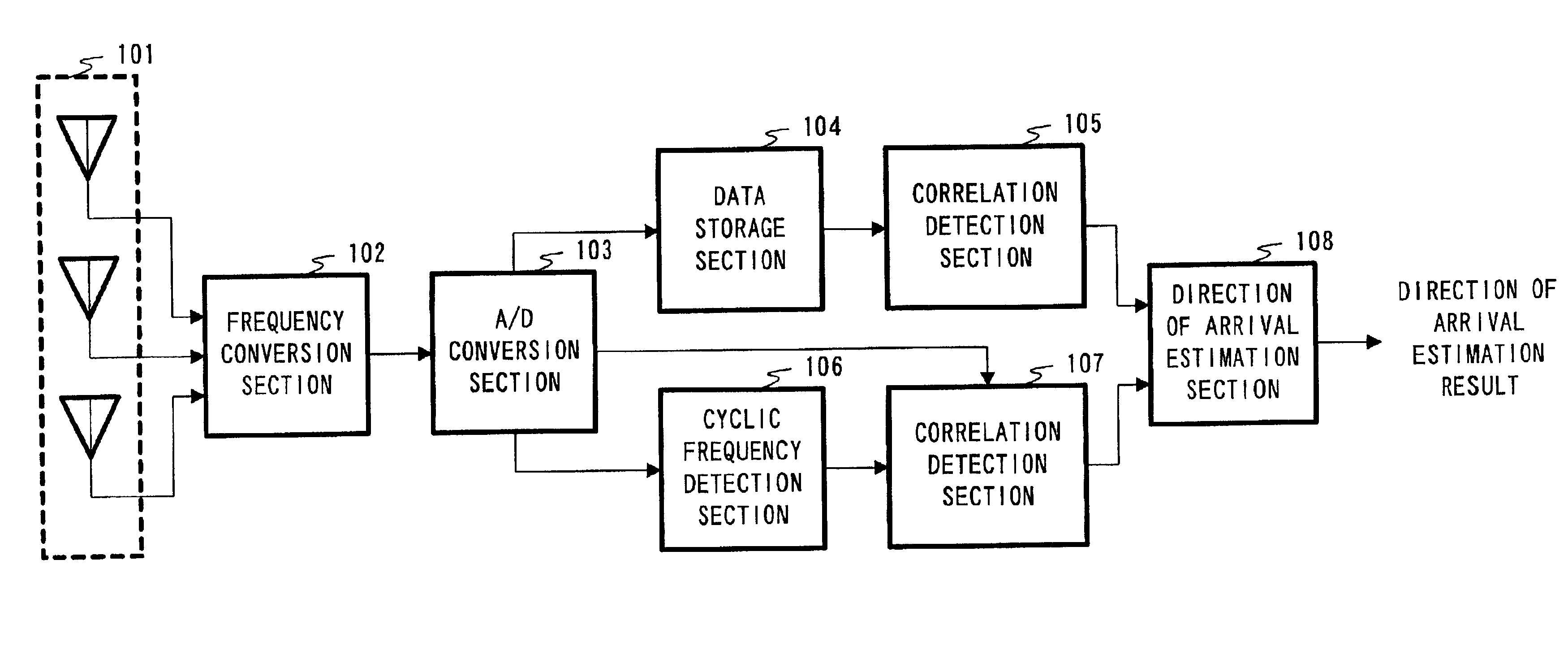
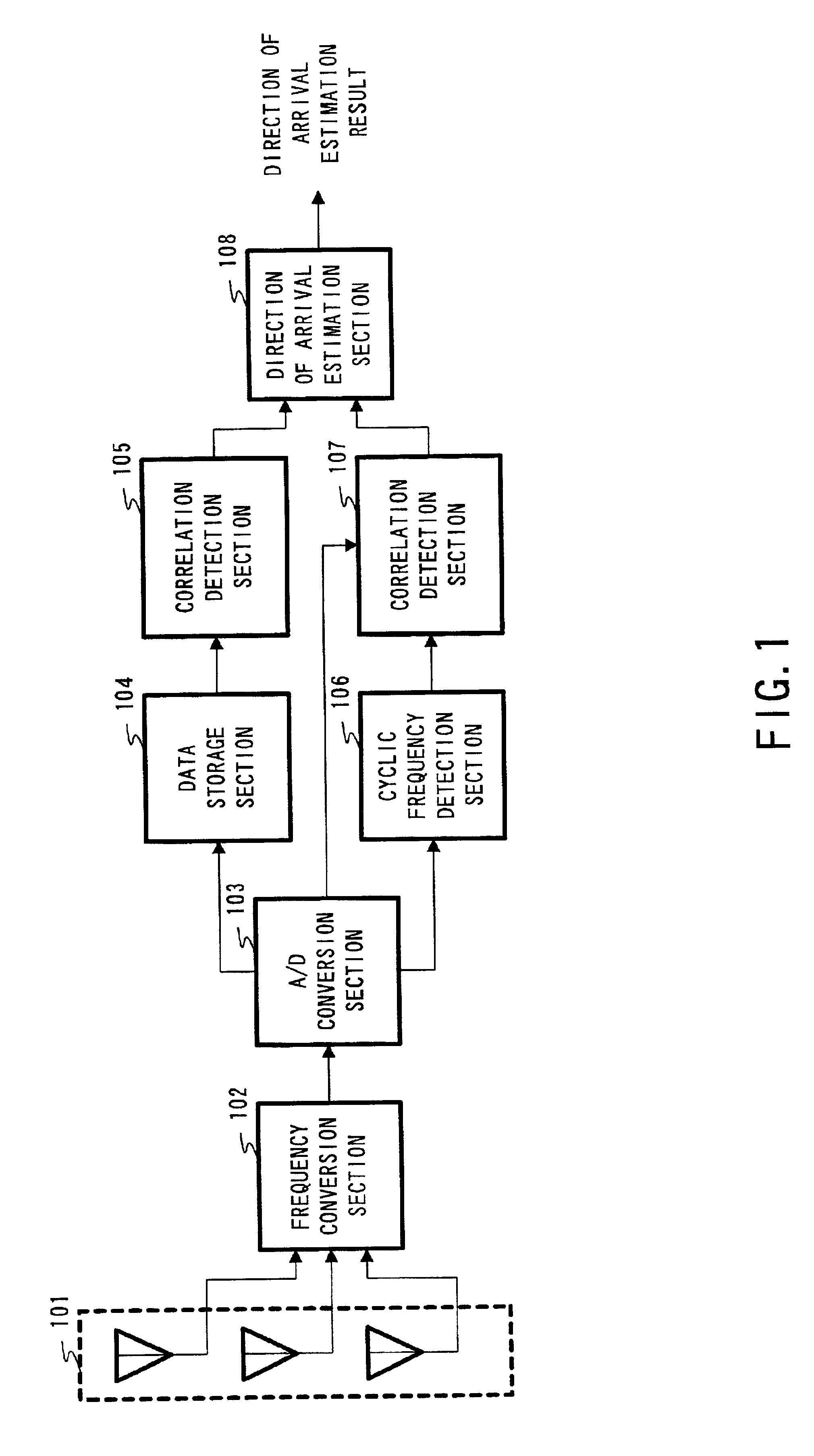
[0017]FIG. 1 is a block connection diagram of a direction of arrival estimator according to Embodiment 1 of the present invention. The direction of arrival estimator shown in FIG. 1 is mainly configured by array antenna 101, frequency conversion section 102, A / D conversion section 103, data storage section 104, correlation detection section 105, cycle frequency detection section 106, correlation detection section 107 and direction of arrival estimation section 108.

[0018]Frequency conversion section 102 converts the frequency of a signal received from a terminal apparatus by array antenna 101 to an intermediate frequency or baseband frequency. A / D conversion section 103 converts the frequency-converted signal to a digital signal.

[0019]Data storage section 104 stores the digital signal output from A / D conversion section 103 until the number of spread spectrum signal chips reaches a predetermined amount (e.g., 100 chips) or more. Correlation detection section 105 uses the...

embodiment 2

(Embodiment 2)

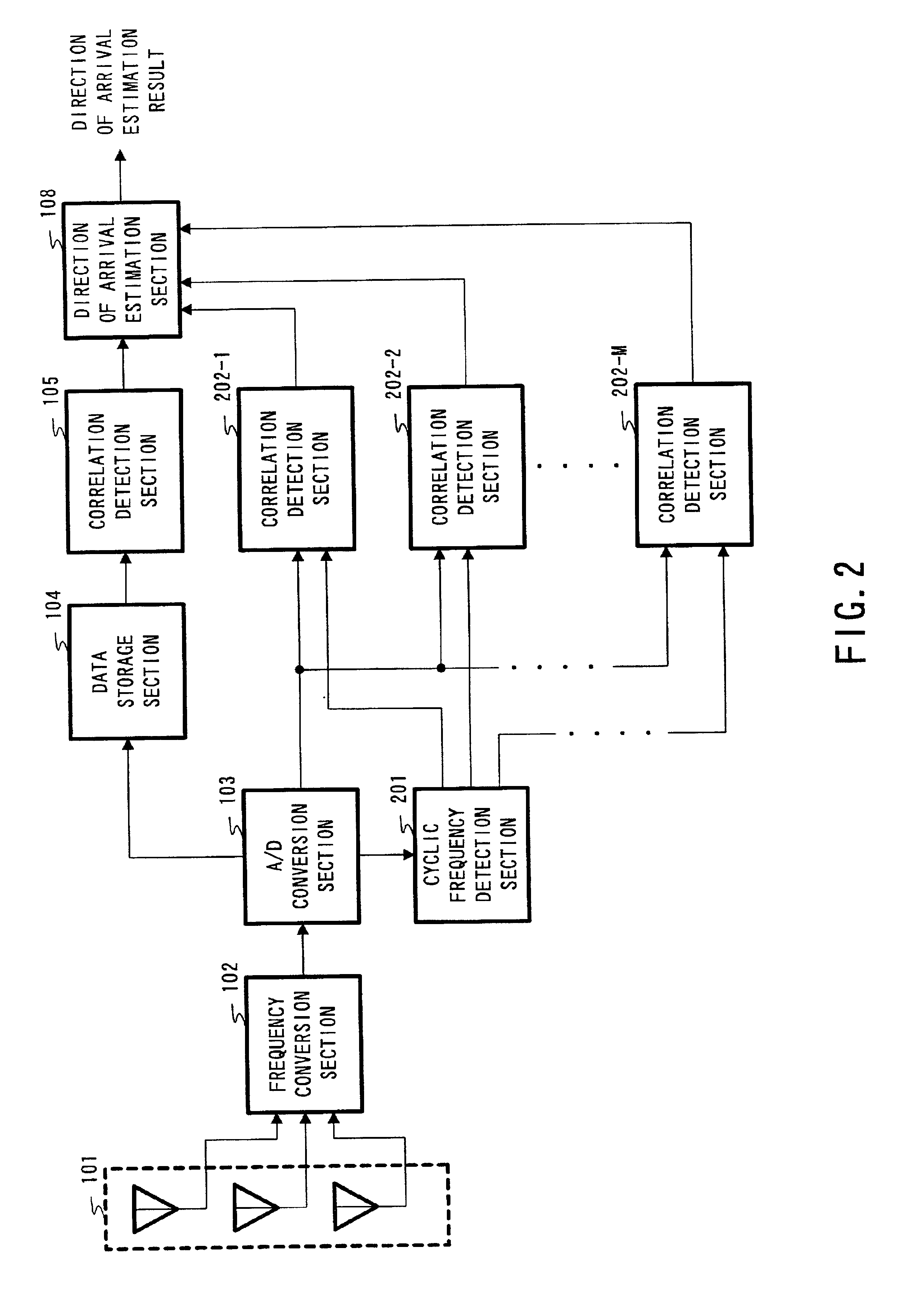
[0027]FIG. 2 is a block connection diagram of a direction of arrival estimator according to Embodiment 2 of the present invention. The components in the direction of arrival estimator in FIG. 2 common to those in FIG. 1 are assigned the same reference numerals as those in FIG. 1 and explanations thereof are omitted.

[0028]The direction of arrival estimator in FIG. 2 differs from that in FIG. 1 in that cycle frequency detection section 201 detects a plurality of cyclic frequencies and M (M: natural number) correlation detection sections 202-1 to 202-M are provided.

[0029]The method of detecting a plurality of cyclic frequencies by cycle frequency detection section 201 includes a method whereby a cyclic auto-correlation function is calculated by changing a cycle frequency using a digital signal made up of a reception signal of one antenna element, a plurality of peak values of the cyclic auto-correlation row, which is the calculation result, is detected and cyclic frequenc...

embodiment 3

(Embodiment 3)

[0033]FIG. 3 is a block connection diagram of a direction of arrival estimator according to Embodiment 3 of the present invention. The direction of arrival estimator in FIG. 3 differs from that in FIG. 1 in that N (N: natural number) array antennas 101-1 to 101-N, N frequency conversion sections 102-1 to 102-N, N A / D conversion sections 103-1 to 103-N, N data storage sections 104-1 to 104-N, N correlation detection sections 105-1 to 105-N, N cycle frequency detection sections 106-1 to 106-N, N correlation detection sections 107-1 to 107-N and N direction of arrival estimation sections 108-1 to 108-N are provided and estimation result comparison section 301 is added.

[0034]FIG. 4 illustrates a positional relationship between array antennas 101-1 to 101-N of the direction of arrival estimator shown in FIG. 3. As shown in FIG. 4, N array antennas are installed in such a way that the direction of the normal to each array antenna forms an angle of 360° / N with the direction o...


PUM


Abstract

An A / D converter converts the signal received by an array antenna and frequency-converted to a digital signal by a frequency converter. A correlation detector uses the chip rate as a cycle frequency and calculates a cyclic correlation matrix of spread spectrum signals stored in data storage. A cycle frequency detector detects the cycle frequency of an interference signal output from A / D converter. A correlation detector uses the detection result of the cycle frequency detector as a cycle frequency and calculates a cyclic correlation matrix of the signal, which becomes an interference signal, using the signal output from A / D converter. A direction of arrival is estimated, using the cyclic correlation matrices calculated by correlation detector and the correlation detector calculates the respective eigenvalues and eigenvectors and estimates the directions of arrival of a spread spectrum signal and a signal, which becomes an interference signal.

Description

BACKGROUND OF THE INVENTION[0001]1. Field of the Invention[0002]The present invention relates to a direction of arrival estimator and direction of arrival estimation method for estimating the direction of arrival of a reception signal using an array antenna.[0003]2. Description of the Related Art[0004]As a method for improving the reception quality of a base station apparatus in a radio communication system, a method of estimating the direction of arrival of a reception signal with an array antenna incorporated and focusing directivity on a desired signal is proposed. Since a signal received by the base station apparatus includes a multitude of interference signals in addition to the desired signal, the base station apparatus needs to separate all signals included in the reception signal and select the desired signal in order to estimate the direction of arrival of the desired signal.[0005]When the base station apparatus carries out radio communication with a plurality of terminal a...

Claims


Application Information

Patent Timeline
Patent Type & Authority Patents(United States)
IPC IPC(8): G01S3/04G01S3/02G01S3/74H01Q3/26G01S3/14G01S3/28G01S7/02H04B1/71H04B7/10H04B7/26H04J13/00H04W16/28H04W24/00
CPCG01S3/043G01S3/74
Inventor YUDA, YASUAKIFUKAGAWA, TAKASHINAKAGAWA, YOUICHIMIMURA, MASAHIRO
Owner PANASONIC CORP
Why Eureka
Try Eureka