Optical configuration for optical fiber switch

Inactive Publication Date: 2005-07-26
INTEL CORP
View PDF48 Cites 23 Cited by
  • Summary
  • Abstract
  • Description
  • Claims
  • Application Information

AI Technical Summary

Benefits of technology

[0015]As a consequence of the low angles of incidence and reflection, the footprints of light beams on the mirrors are nearly circular. This allows the advantageous use of small, nearly circular mirrors which have low inertia and are thus easier to move than larger or substantially non-circular mirrors. In addition, nearly-circular mirrors deform less than substantially non-circular mirrors upon application of a coating, such as a reflective coating.
[0016]Another embodiment includes a beam splitter located in an optical path between the first plurality of ports and the first plurality of mirrors. This beam splitter may, for example, direct a portion of light output by one of the first plurality of ports to a detector and thereby provide input signal (e.g. telecommunication light be

Problems solved by technology

As optical fiber progressively supplements and replaces metal wire as the backbone of telecommunications networks, the switches that route optical signals have emerged as a significant bottleneck.
Electronic switching requires light to be converted to an ele

Method used


Image

  • Optical configuration for optical fiber switch
  • Optical configuration for optical fiber switch
  • Optical configuration for optical fiber switch

Examples


Example

[0035]Like reference numbers in the various figures denote same parts in the various embodiments. Dimensions in the figures are not necessarily to scale.

DETAILED DESCRIPTION

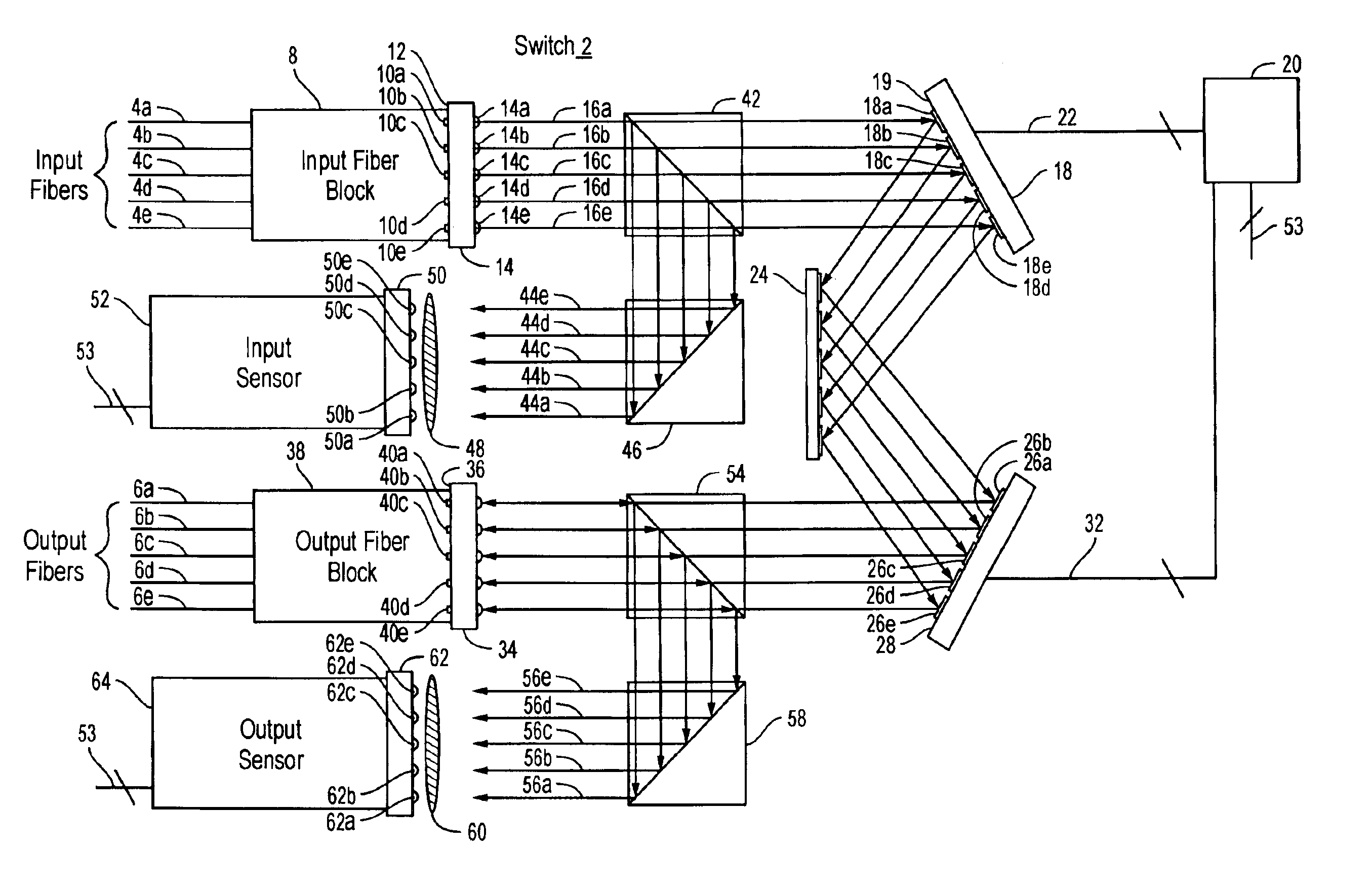
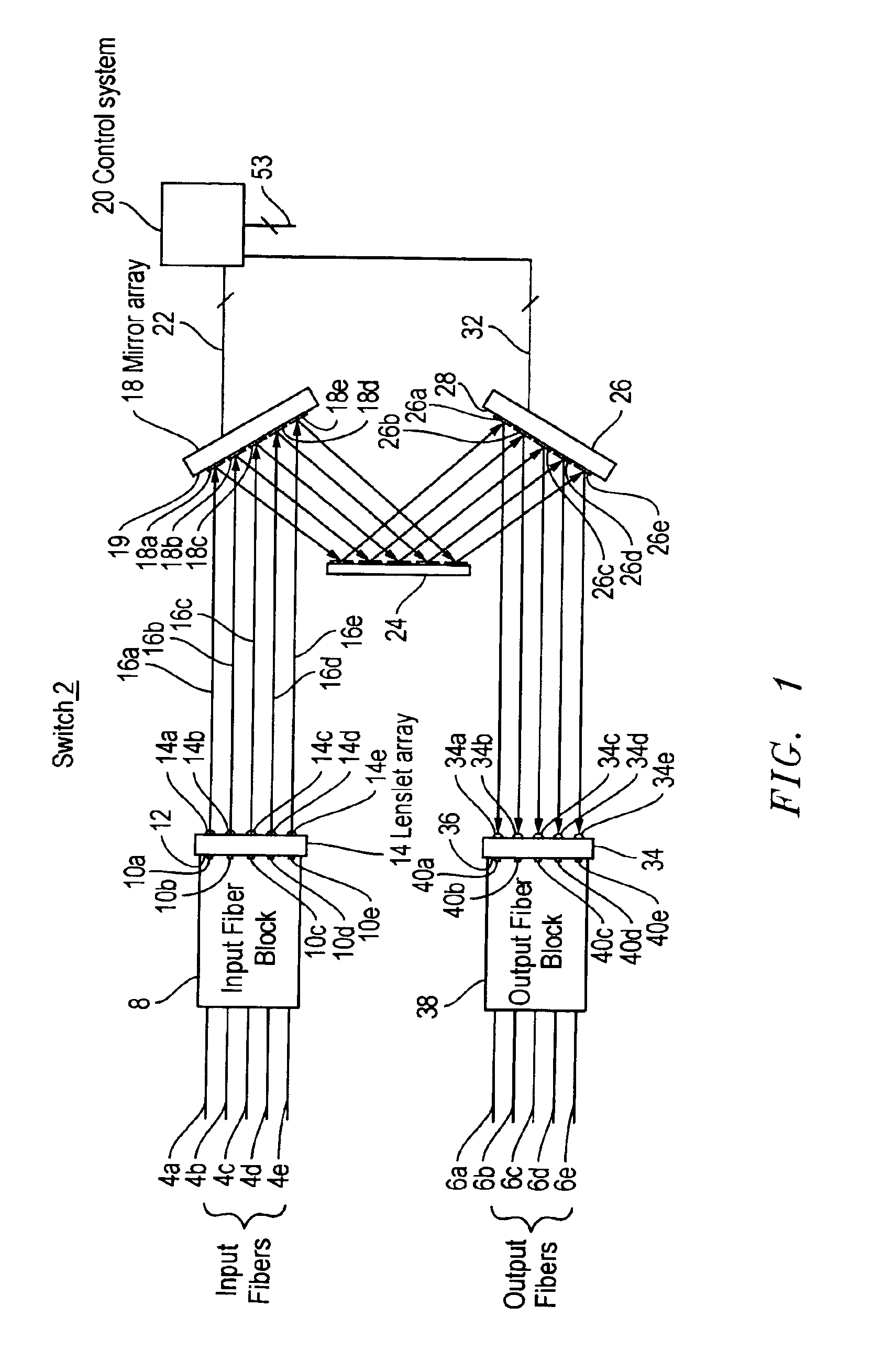
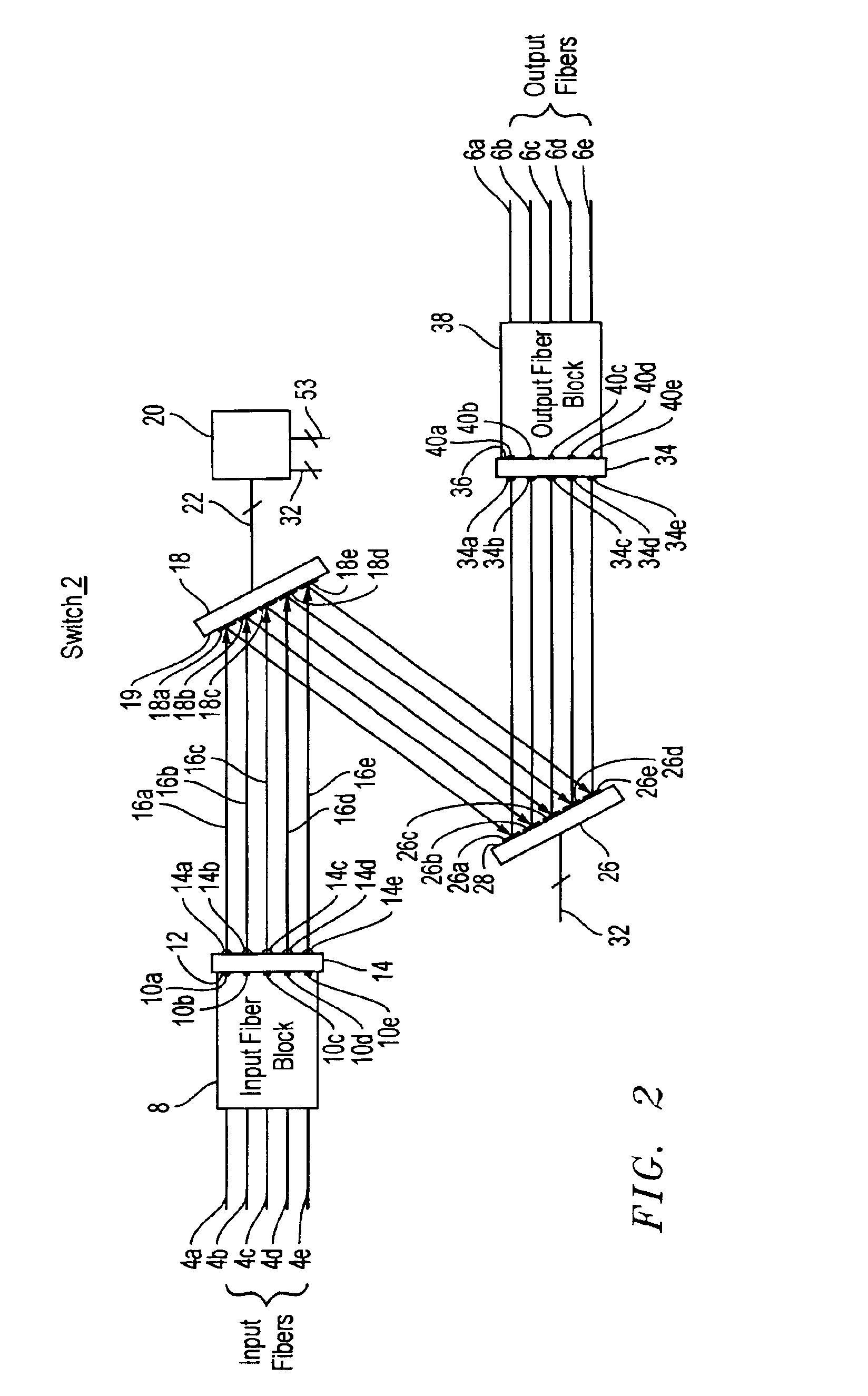
[0036]An optical fiber cross-connect switch in accordance with embodiments of the present invention routes light input through any one of N input ports to any one of P output ports. In a typical optical path through a switch, light entering the switch through an input port is incident on a corresponding first micro-mechanical mirror in a first two dimensional array of micro-mechanical mirrors. The first micro-mechanical mirror, which can be oriented in a range of arbitrary directions (dθ,dφ), is tilted to direct the light to a second micro-mechanical mirror in a second two dimensional array of micro-mechanical mirrors. The second micro-mechanical mirror, which can also be oriented in a range of arbitrary directions (dθ,dφ), is tilted to direct the light to a corresponding output port and hence out of the switch.

[...


PUM


Abstract

An optical fiber switch in accordance with an embodiment of the present invention includes a first plurality of ports, a second plurality of ports, a first plurality of mirrors disposed on a first surface, and a second plurality of mirrors disposed on a second surface. Each one of the first plurality of mirrors is individually controllable to direct light output from a corresponding one of the first plurality of ports to any one of the second plurality of mirrors. Each one of the second plurality of mirrors is individually controllable to direct to a corresponding one of the second plurality of ports light incident on it from any one of the first plurality of mirrors. Advantageously, optical fiber switches in accordance with embodiments of the present invention may couple more than a thousand input ports to more than a thousand output ports with an insertion loss of less than about 3 decibels.

Description

CROSS REFERENCE TO RELATED APPLICATIONS[0001]This application is related to the following, commonly assigned, U.S. patent applications: U.S. patent application Ser. No. 9 / 999,610, U.S. patent application Ser. No. 09 / 999,705, U.S. patent application Ser. No. 09 / 866,063, U.S. patent application Ser. No. 10 / 003,659, issued as U.S. Pat. No. 6,614,954, U.S. patent application Ser. No. 10 / 002,310, issued as U.S. Pat. No. 6,636,656, all of which are incorporated herein by reference. This application is also related to U.S. patent application Ser. No. 09 / 779,189, now U.S. Pat. No. 6,480,320 entitled “A Microelectromechanical Mirror,” filed Feb. 7, 2001, assigned to the assignee of the present invention, and incorporated herein by reference.BACKGROUND OF THE INVENTION[0002]1. Field of the Invention[0003]The present invention relates to optical fiber cross-connect switching.[0004]2. Description of the Related Art[0005]As optical fiber progressively supplements and replaces metal wire as the b...

Claims


Application Information

Patent Timeline
IPC IPC(8): H04Q11/00
CPCH04Q11/0005H04Q2011/0026
Inventor HUANG, CHENG-CHUNGNASIRI, STEVEN SAEEDSPRAGUE, RANDALL BRIANHARWIT, ALEXBAKIN, DMITRY VASILYBRYZEK, JANUSZ
Owner INTEL CORP
Why Eureka
Try Eureka