DC motor power-on device and valve device using the same

A technology of energizing device and valve device, which is applied to electromechanical devices, electric components, DC commutators, etc., can solve the problems of poor valve opening and closing action reactivity, etc., to improve reliability, improve wiring efficiency, and improve Effects of Wiring Work

Inactive Publication Date: 2008-10-01
MITSUBISHI ELECTRIC CORP
View PDF1 Cites 0 Cited by
  • Summary
  • Abstract
  • Description
  • Claims
  • Application Information

AI Technical Summary

Problems solved by technology

[0009] The structure of the conventional valve device is as described above. Since the motor shaft P13 screwed in the rotor P2 is moved up and down by the rotation of the rotor P2, the valve member P17 is brought into contact with the sealing member P18 through the valve drive shaft P15. Therefore, it is necessary to insert the motor shaft P13 into the rotor P2, and since the winding P5 must be wound on the outer circumference of the rotor P2, there is an increase in the outer diameter of the rotor P2, which increases the inertia torque, and the valve The problem that the responsiveness of the opening and closing action deteriorates

Method used


Image

  • DC motor power-on device and valve device using the same
  • DC motor power-on device and valve device using the same
  • DC motor power-on device and valve device using the same

Examples


Embodiment 1

[0051] Embodiments of the present invention will be described below with reference to the accompanying drawings.

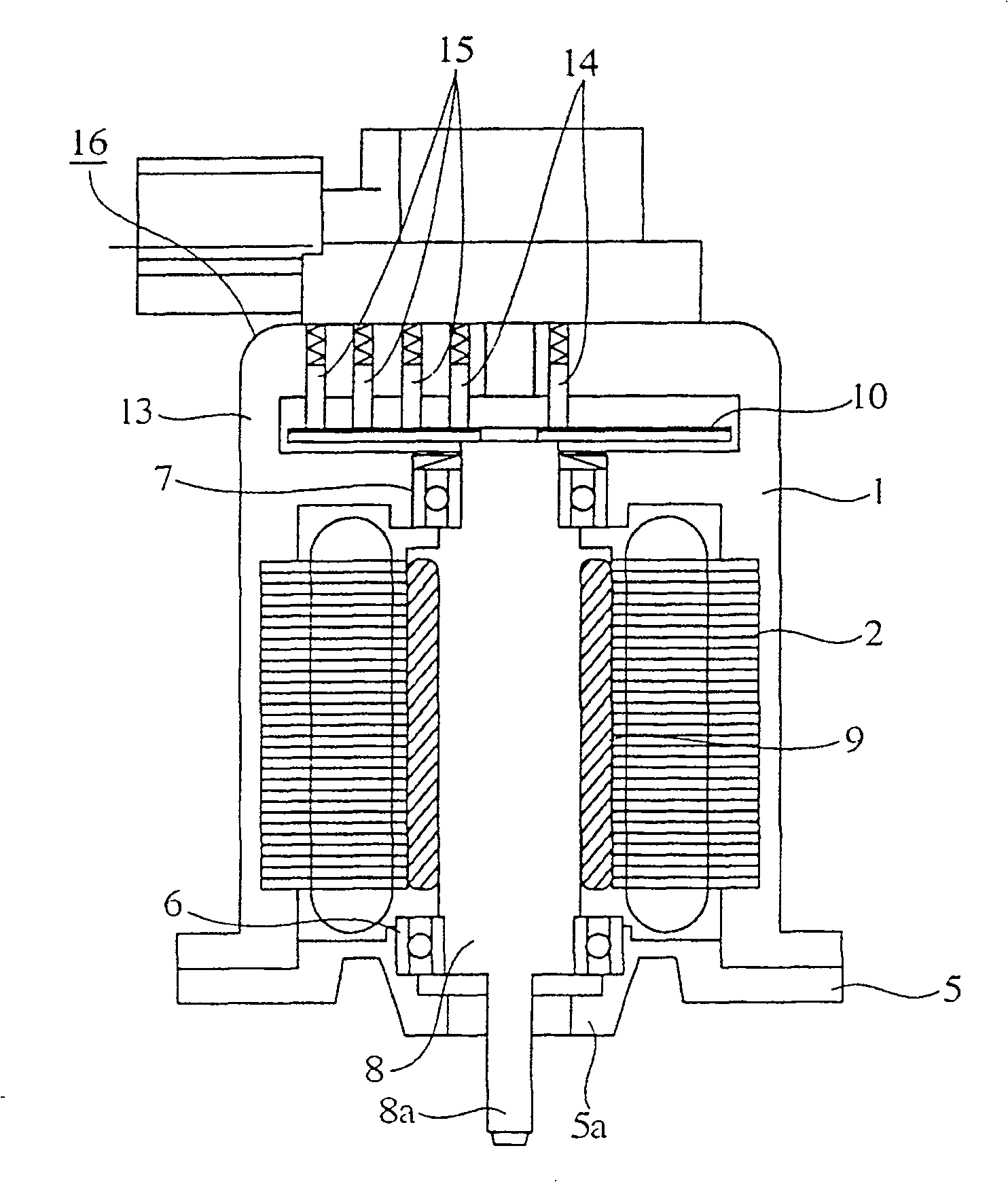
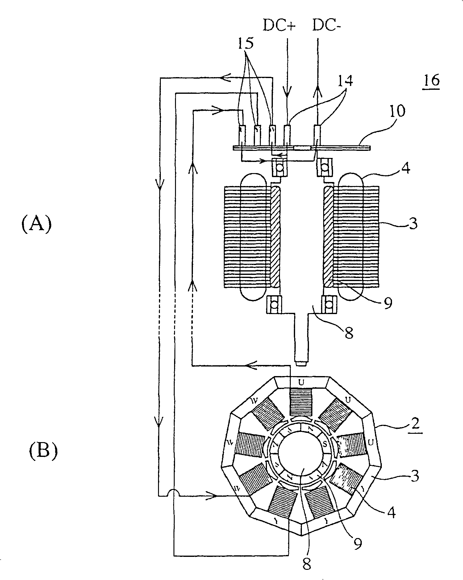
[0052] figure 2 It is a cross-sectional view showing the structure of a DC motor energizing device according to Embodiment 1 of the present invention, image 3 express figure 2 The current flow in the energized device, image 3 (A) is a sectional view, image 3 (B) is a plan view, and Fig. 4 shows figure 2 The three-dimensional view of the structure of the commutator and collector ring shown, Figure 5 yes means figure 2 A top view of the stator fabrication method.

[0053] In the figure, 1 is a motor casing formed of a resin material, and 2 is a stator integrally formed with the motor casing 1 by resin molding, such as Figure 5 As shown in (A), the iron core pieces 3b on which the magnetic pole teeth 3a protrude respectively are configured in such a way that a predetermined number of magnetic materials connected by thin-walled parts 3c are laminated t...

Embodiment 2

[0060] Fig. 6 is the perspective view that shows the structure of the energizing part of the DC motor energizing device of embodiment 2 of the present invention, Fig. 7 is the perspective view showing the commutator structure in Fig. 6, Fig. 8 shows the structure of the slip ring among Fig. 6, Fig. 8 ( A) is a perspective view showing the front, and FIG. 8(B) is a perspective view showing the back.

[0061] In the figure, 17 is the same as the above-mentioned embodiment 1, and is fixed on the other end side of the rotor 8 and rotates with the disc 8, as shown in Figure 8, 18 is to leave the central part 17a of the disc 17, on the outer periphery The side is divided into 3 concentric ring-shaped collector rings.

[0062] As shown in FIG. 7, 19 is a commutator, which includes commutator segments 19a formed by dividing the cylindrical member into a plurality of (12 in the figure) along the circumferential direction, and commutator segments 19a respectively extending to the respec...

Embodiment 3

[0065] Fig. 9 is a perspective view showing the structure of the energizing part of the DC motor energizing device according to Embodiment 3 of the present invention. Fig. 10 shows the structure of the first energizing member in Fig. 9. Fig. 10 (A) is a perspective view, and Fig. 10 (B) It is an expanded view, and Fig. 11 shows the structure of the second energized member among Fig. 9, and Fig. 11 (A) is a perspective view, and Fig. 11 (B) is an expanded view, Figure 12 Represent the structure of the 3rd electrification member in Fig. 9, Figure 12 (A) is a perspective view, Figure 12 (B) is an expanded view, Figure 13 is indicated in Figure 10 to Figure 12 A top view of an example of the method of forming the first, second, and third conductive members.

[0066] In the figure, as shown in FIG. 10(A), 23 is a first current-carrying member, which is formed by bending a ring-shaped member 23a and a plurality of rectangles vertically at a predetermined length away from the...


PUM


Abstract

A device for energizing a DC motor having a commutator segmented into pieces in a circumferential direction to commutate the DC current that is fed from a power source via a first brush and a slip ring that is segmented into n parts in a concentric ring shape around the commutator, each part of which is electrically connected to each piece of the commutator so as to apply to the coils of the stator currents that are commutated into n phases by the commutator, thereby enhancing the reliability. A valve device comprising a device for energizing a DC motor having a stator in which a specified number of coils are arranged circumferentially at generally regular intervals around a stator core, a rotor in which a plurality of permanent magnetic poles are arranged in positions corresponding to the coils of the stator on the outer peripheral surface, an energizing means for energizing the coils of the stator by commutating the DC current fed from a power source via the rotor, an axial member disposed in the center part of the rotor and movable axially in response to the rotation of the rotor, and a valve member capable of opening and closing by the movement of the axial member, thereby achieving a small inertia of the rotor and excellent response of the opening/closing actions of the valve.

Description

[0001] This application is a divisional application of the applicant Mitsubishi Electric Corporation, the application number is 00801395.0 (the international application number is PCT / JP 00 / 04680), and the title is "DC motor energizing device and valve device using DC motor energizing device". technical field [0002] The present invention relates to a DC motor energizing device that rectifies the DC current from a power supply by a commutator, and then passes the rectified current through a collector ring to energize each winding of the stator, and uses a DC motor driven device for exhaust gas, etc. A valve device of a DC motor energizing device that opens and closes a passage or opening of a fluid. Background technique [0003] Such an existing DC motor energizing device is disclosed in, for example, Japanese Invention Patent Publication No. 289520 in 1996. The inside of the commutator is equipped with a collector ring that is divided into concentric rings, and the DC curr...

Claims


Application Information

Patent Timeline
Patent Type & Authority Patents(China)
IPC IPC(8): H02K13/00H01R39/10H02K5/14H02K7/06H02K7/14H02K23/62
CPCH02K5/14H02K7/14H02K7/06H02K23/62H01R39/10H02K3/50H02K13/00
Inventor 藤田阳一八木修三宅俊彦三好帅男中原祐治大重丰实
Owner MITSUBISHI ELECTRIC CORP
Why Eureka
Try Eureka