
Efficient adaptive feedforward periodic disturbance compensation

a periodic disturbance compensation and adaptive technology, applied in adaptive control, process and machine control, instruments, etc., can solve problems such as non-circular data tracks, performance variations, and other systems suffering from the effects

Inactive Publication Date: 2005-07-26
TOKYO ELECTRON LTD
View PDF16 Cites 13 Cited by
  • Summary
  • Abstract
  • Description
  • Claims
  • Application Information

AI Technical Summary

Benefits of technology

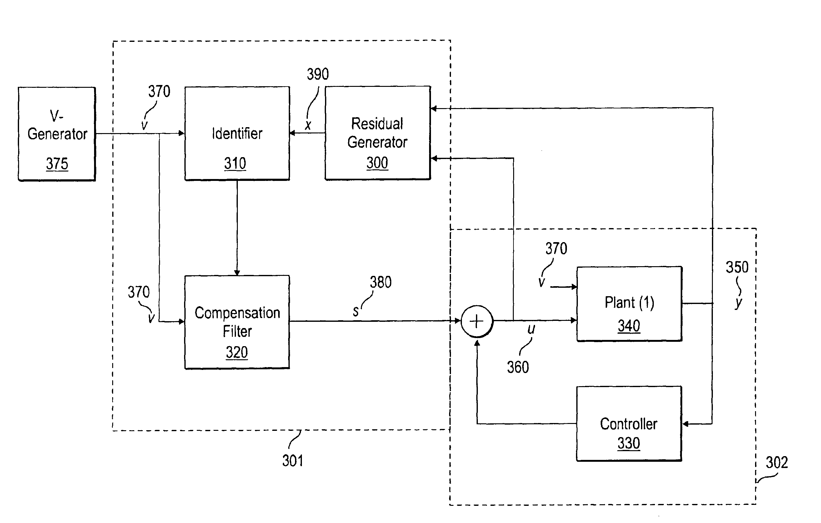
[0011]A system and method is given for minimizing periodic disturbances in electronic systems. Given the input-output characteristics of the electronic system, the present system identifies and cancels the periodic disturbance. The periodic disturbance parameters are identified through the use of a residual generator. The output of the residual generator is fed into an identifier that estimates disturbance parameters. The compensation filter combines the output of the identifier with a set of pre-computed parameters to form a cancellation signal. This signal is then added to the input of the plant to cancel the periodic disturbance.

Problems solved by technology

Unmeasured variables may affect the operation of a drive and can cause variations in performance from unit to unit, as well as within a unit during use of the drive.
However, small errors are made during the servo writing process that result in data tracks that are slightly non-circular.
Other systems suffer from the effects of periodic disturbances as well.
As a result, they do not differentiate between periodic disturbances and signals that are created by the feedback control system.
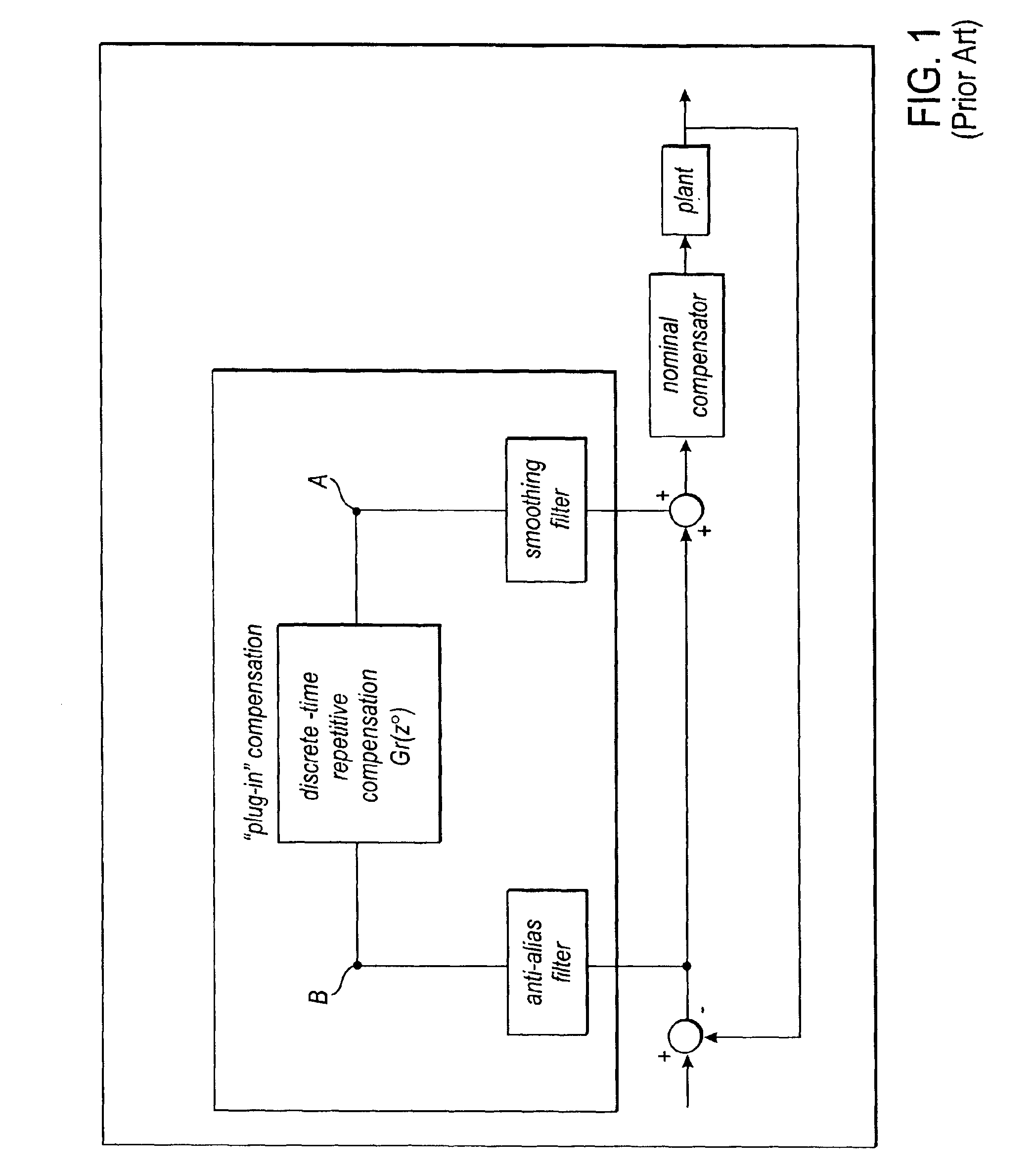
The system in FIG. 1 is a feedback compensator and does not allow feed forward cancellation as does the system in FIG.
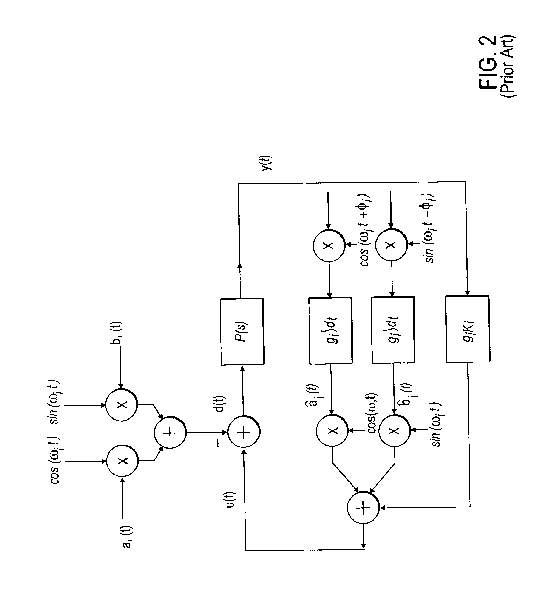
However, the prior art system of FIG. 2 only uses the output of their plant y(t) in its controller.
Furthermore, the prior art system of FIG. 2 fails to account for the input / output behavior of the plant.
The RRO compensation methods are particularly difficult for CD-ROM drives.
CD players and DVD drives because the error caused by RRO changes every time a disk is inserted into a drive.
Furthermore, the error caused by RRO in CD-ROMs, DVDS, and CDs, changes over time based upon the changing rotational velocity of the disk, thus complicating RRO compensation methods.

Method used


Image

  • Efficient adaptive feedforward periodic disturbance compensation
  • Efficient adaptive feedforward periodic disturbance compensation
  • Efficient adaptive feedforward periodic disturbance compensation

Examples


Embodiment Construction

[0022]A method and apparatus for Adaptive Feed-Forward Disturbance Cancellation is disklosed. In the following description, for purposes of explanation, specific nomenclature is set forth to provide a thorough understanding of the present techniques. However, it will be apparent to one skilled in the art that these specific details are not required in order to practice the present techniques. For example, the elements of the present techniques described may implement embodiments utilizing all hardware or any combination of hardware and software.

[0023]Disturbances associated with systems having rotating parts may be characterized as Repeatable-Run-Out (RRO) or Non-Repeatable-Run-Out (NRRO). RRO disturbances are periodic and phase-locked to the angular position of the rotating parts. By way of example in a hard disk drive, if a fixed point were marked on the disk, RRO would cause the magnetic head to be misaligned with the fixed point by the same amount on every rotation. In contrast,...


PUM


Abstract

A system and method is given for minimizing periodic disturbances in electronic systems. Given the input-output characteristics of the system, the present method identifies and cancels the periodic disturbance. The periodic disturbance parameters are identified through the use of a residual generator. The output of the residual generator is fed into an identifier that estimates disturbance parameters. The compensation filter combines the output of the identifier with a set of pre-computed parameters to form a cancellation signal. This signal is then added to the input of the plant to cancel the periodic disturbance.

Description

[0001]This application is a continuation of application Ser. No. 09 / 517,948, filed on Mar. 3, 2000, now U.S. Pat. No. 6,684,114.FIELD OF THE INVENTION[0002]The present invention relates to the field of control systems. In particular the present invention diskloses a system and method for minimizing periodic disturbances.BACKGROUND OF THE INVENTION[0003]Many controlled physical systems include rotating parts. Some examples include machine tools such as CNC lathes and routers as well as rotating data storage products for computers and consumer electronics. In particular, rotating storage devices include hard disk drives, CD players, CD-ROM drives, and DVD players. Accurate control over the position of the data read / write mechanism is critical to the operation of a rotating media storage product. For example, in a hard disk drive system data is stored in magnetic circular tracks on a media platter. Data is read and written by a magnetic head that floats over the circular tracks.[0004]U...

Claims


Application Information

Patent Timeline
Patent Type & Authority Patents(United States)
IPC IPC(8): G05B13/04G05B5/00G05B5/01G05B21/02G05B21/00
CPCG05B5/01G05B13/042G05B21/02
Inventor ERICKSON, MARK A.GALARZA, CECILIAHERNANDEZ, DANSHAH, SUNIL C.
Owner TOKYO ELECTRON LTD
Learn More