Eureka AIR delivers breakthrough ideas for toughest innovation challenges, trusted by R&D personnel around the world.

Device and method for automatically detecting a calibration termination for a geomagnetic sensor

a geomagnetic sensor and automatic detection technology, applied in magnetic measurements, liquid/fluent solid measurements, instruments, etc., can solve the problems of inability to estimate the position around buildings or in tunnels, easy to affect the geomagnetic sensor, and position errors as high as 100 meters

Active Publication Date: 2005-07-26
SAMSUNG ELECTRONICS CO LTD
View PDF4 Cites 30 Cited by
  • Summary
  • Abstract
  • Description
  • Claims
  • Application Information

AI Technical Summary

Benefits of technology

[0017]Preferably, the detection step detects the number of revolutions Ns of the geomagnetic sensor when the geomagnetic sensor revolves more than once for calibration implementation of the geomagnetic sensor.
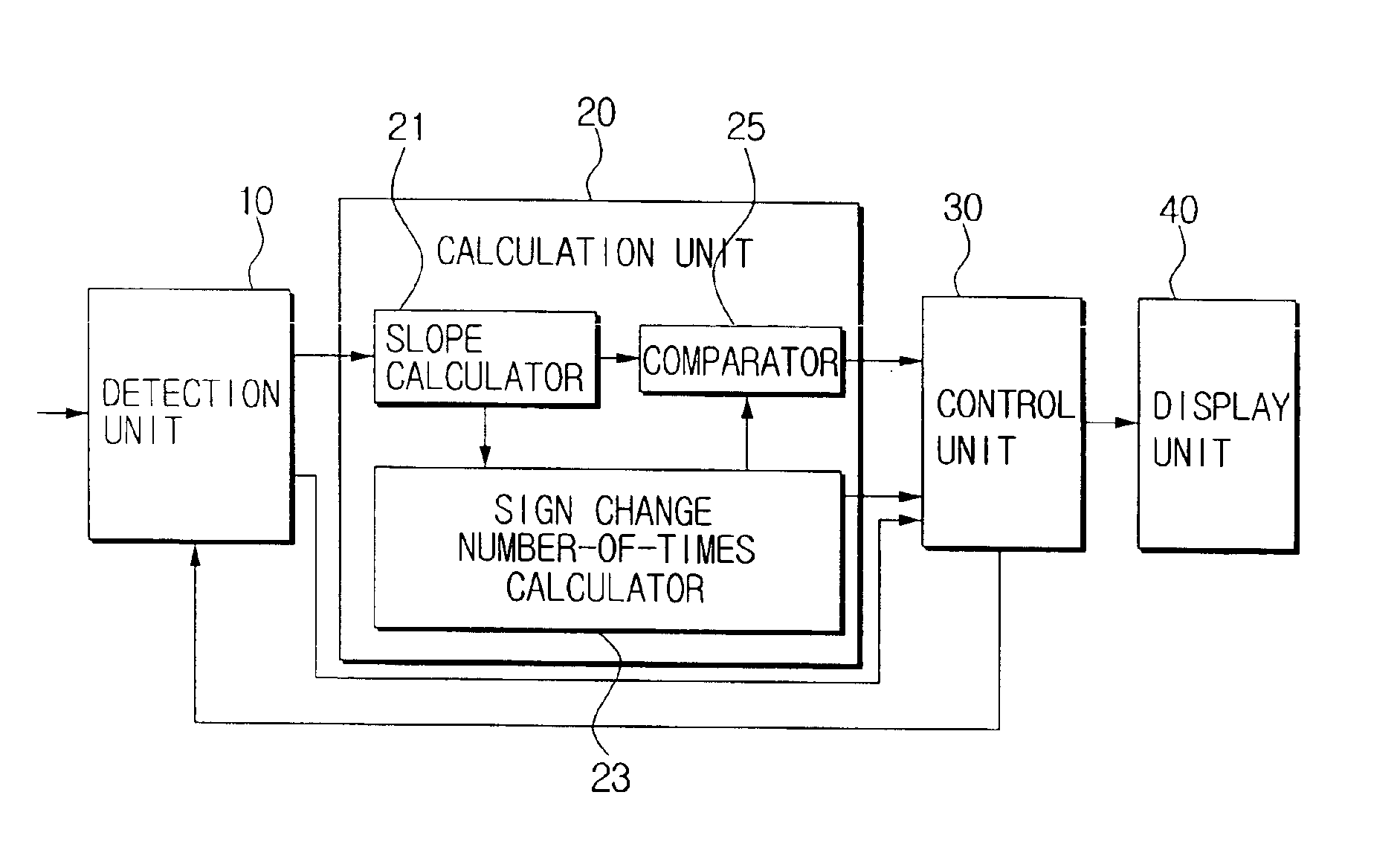
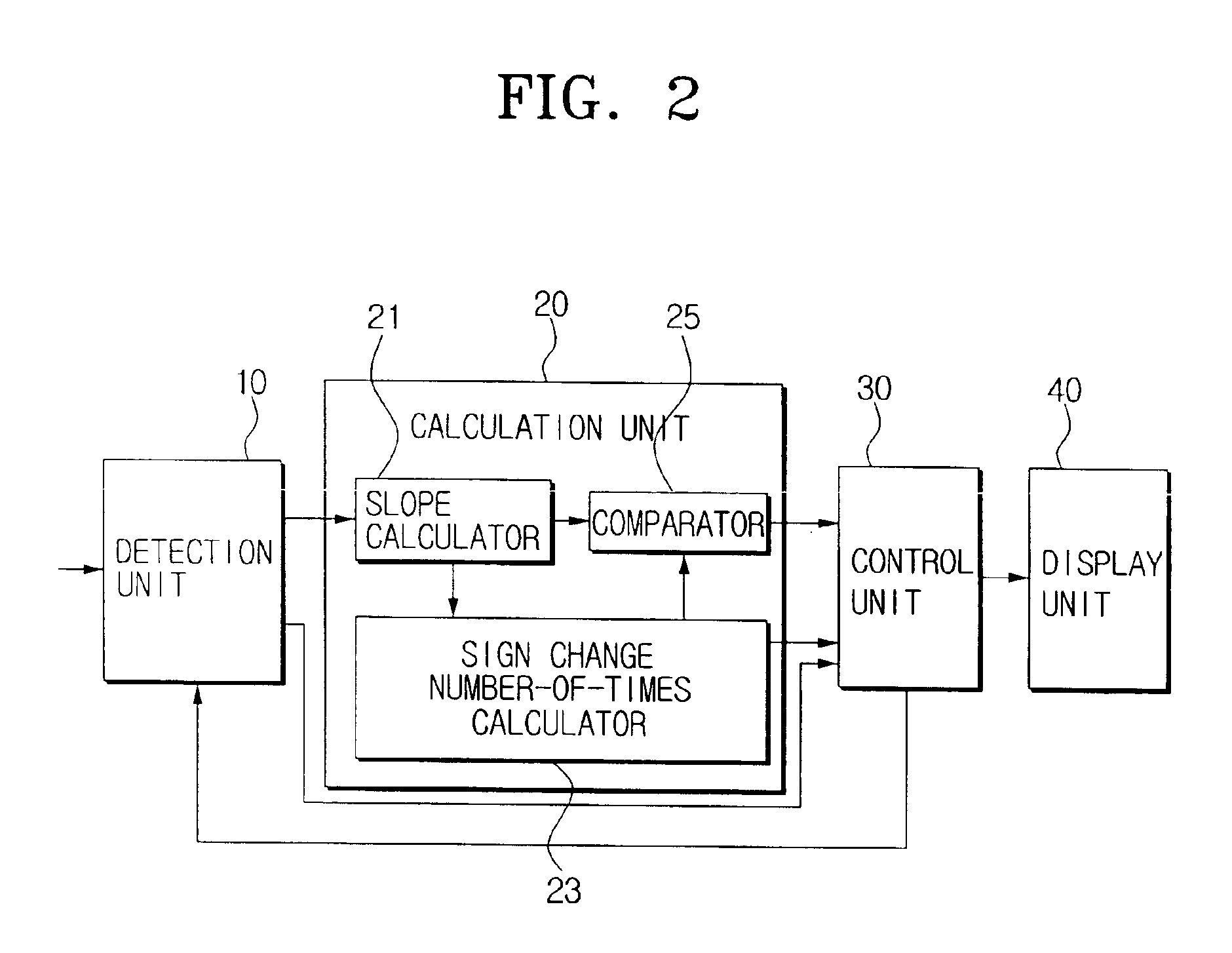
[0018]Preferably, the decision step outputs a corresponding signal to display the calibration progress state on a display unit when the number of sign changes Nx of the slope dX/dt of the signal X and the number of sign changes Ny of the slope dY/dt of the signal Y are both less than 2Ns.
[0019]Further, the

Problems solved by technology

However, GPS has limitations in that it is not able to estimate positions around buildings or in tunnels where electric waves are not received, has a position error of as much as 100 meters, among others.
However, the geomagnetic sensor is easily affected by ambient magnetic fields of buildings, iron bridges, subway trains, and other similar sources, and the output signals of the geomagnetic sensor vary frequently depending upon an assembly state, declined degrees, or measurement environments of the sensor.
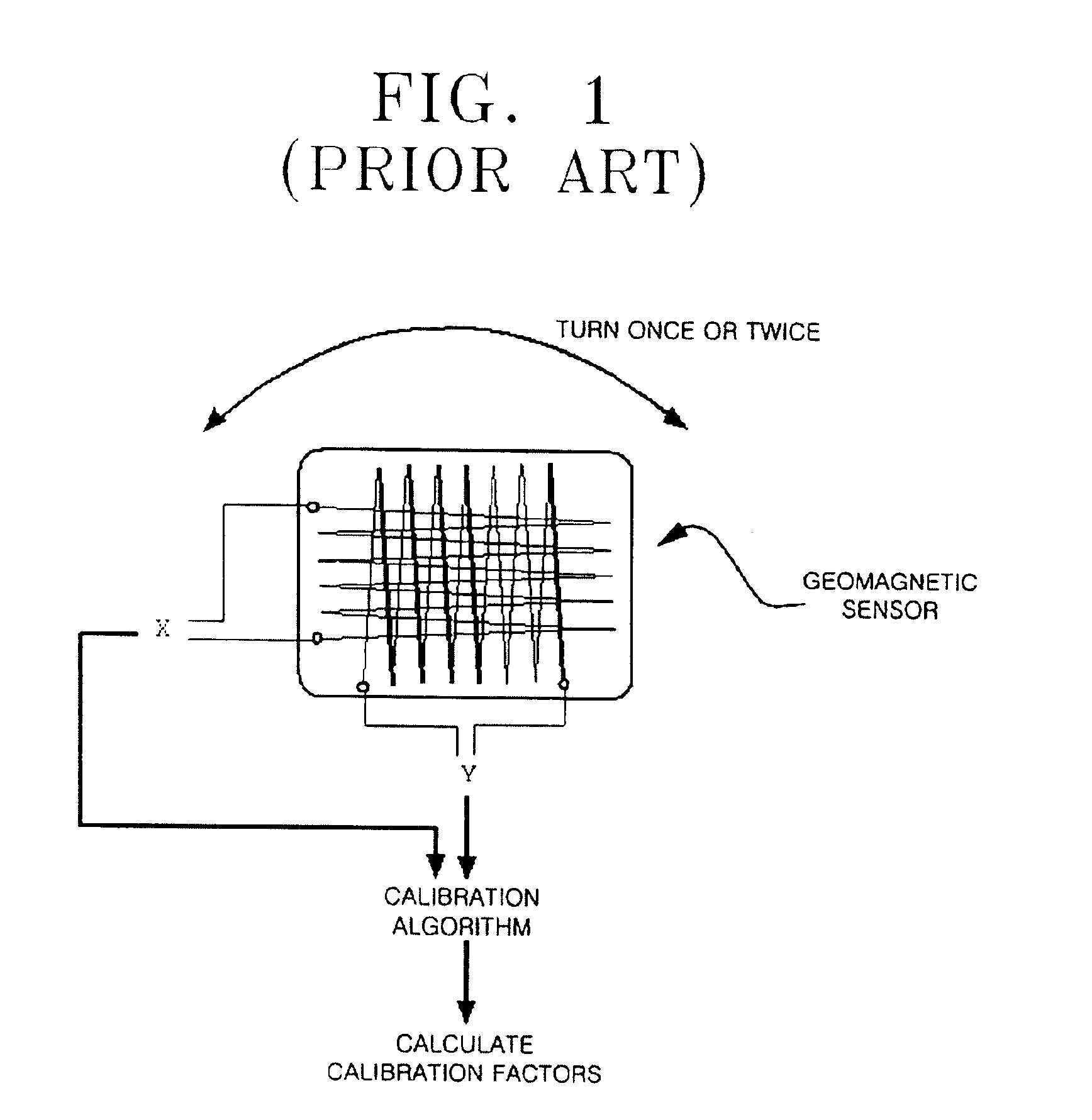
This method does not provide an easy calibration process since the user does not know the progress of the calibration process, i.e., the calibration progress state, which often leads to the calibration process not being properly performed.
Accordingly, since the maximum and minimum values change depending upon calibration environments and the errors of the calibration factors are induced when the changing values are used in monitoring the calibration process, situations occur when the sensor is not able to detect precise calibration factors nor calculate the termination of the calibration process, i.e., the calibration termination state.

Method used


Image

  • Device and method for automatically detecting a calibration termination for a geomagnetic sensor
  • Device and method for automatically detecting a calibration termination for a geomagnetic sensor
  • Device and method for automatically detecting a calibration termination for a geomagnetic sensor

Examples


Embodiment Construction

[0028]Korean Patent Application No. 2002-74890, filed on Nov. 28, 2002, and entitled: “Device and Method for Automatically Detecting a Calibration Termination for a Geomagnetic Sensor,” is incorporated by reference herein in its entirety.

[0029]The present invention will now be described more fully hereinafter with reference to the accompanying drawings, in which a preferred embodiment of the invention is shown. The invention may, however, be embodied in different forms and should not be construed as limited to the embodiments set forth herein. Rather, these embodiments are provided so that this disclosure will be thorough and complete, and will fully convey the scope of the invention to those skilled in the art. Like numbers refer to like elements throughout.

[0030]FIG. 2 is a block diagram for showing a device for automatically detecting a calibration termination of a geomagnetic sensor according to an embodiment of the present invention. In FIG. 2, a device for automatically detect...


PUM


Abstract

A device for automatically detecting a calibration termination of a geomagnetic sensor includes a detection unit for detecting signals X and Y outputted from X-axis and Y-axis coils of the geomagnetic sensor, respectively, a calculation unit for calculating slopes dX / dt and dY / dt of the signals X and Y, respectively, and the number of sign changes Nx and Ny of the slope dX / dt of the signal X and the slope dY / dt of the signal Y, respectively, a display unit for displaying the calibration termination and a calibration progress state for the geomagnetic sensor, and a control unit for outputting a driving signal to the display unit to display a state of the calibration termination based on the slope dX / dt of the signal X and the slope dY / dt of the signal Y and the number of slope sign changes Nx and Ny.

Description

BACKGROUND OF THE INVENTION[0001]1. Field of the Invention[0002]The present invention relates to a device and a method for automatically detecting the termination of a calibration of a geomagnetic sensor. More particularly, the present invention relates to a device and a method capable of detecting the progress of a calibration using slopes of signals outputted from a geomagnetic sensor and the number of slope sign changes, and automatically terminating the calibration.[0003]2. Description of the Related Art[0004]A geomagnetic sensor is a direction search means, and is used in an electronic compass, navigation systems, satellite antenna controls, robot direction controls, game devices, portable terminals, personal digital assistants (PDAs), notebooks, and the like. As alternatives to a geomagnetic sensor, there are speed sensors, gyro sensors, global positioning systems (GPS), and so on, for use as direction search means. In particular, GPS is a world-wide position-determining syste...

Claims


Application Information

Patent Timeline
IPC IPC(8): G01C17/38G01C17/00
CPCG01C17/38
Inventor CHO, WOO-JONGCHOI, SANG-ON
Owner SAMSUNG ELECTRONICS CO LTD
Why Eureka
Eureka Blog
Learn More