Controlled large signal capacitor and inductor

a large signal and capacitor technology, applied in the direction of discontinuous tuning by electric means, automatic control of pulses, television systems, etc., can solve the problems of poor control input dynamic behavior, system instability, and difficult generation of control signals,

Active Publication Date: 2014-10-07
REHM MARKUS
View PDF13 Cites 5 Cited by
  • Summary
  • Abstract
  • Description
  • Claims
  • Application Information

AI Technical Summary

Problems solved by technology

The design of switched circuit concepts, that fulfill all these requirements and remain operational far into the high frequency range, is a real challenge.
The generation of control signals, which shall be dependent on the controlled signal itself is very difficult.
The main problem is that altering the output signal instantly changes the input value and can thus make the system unstable.
The eminent disadvantage of this method is a poorer dynamic behavior with respect to the control input.
Furthermore, the diodes generate transients in the transition interval from blocking to conduction mode and vice versa, interferences and therefore additional losses.

Method used


Image

  • Controlled large signal capacitor and inductor
  • Controlled large signal capacitor and inductor
  • Controlled large signal capacitor and inductor

Examples


Embodiment Construction

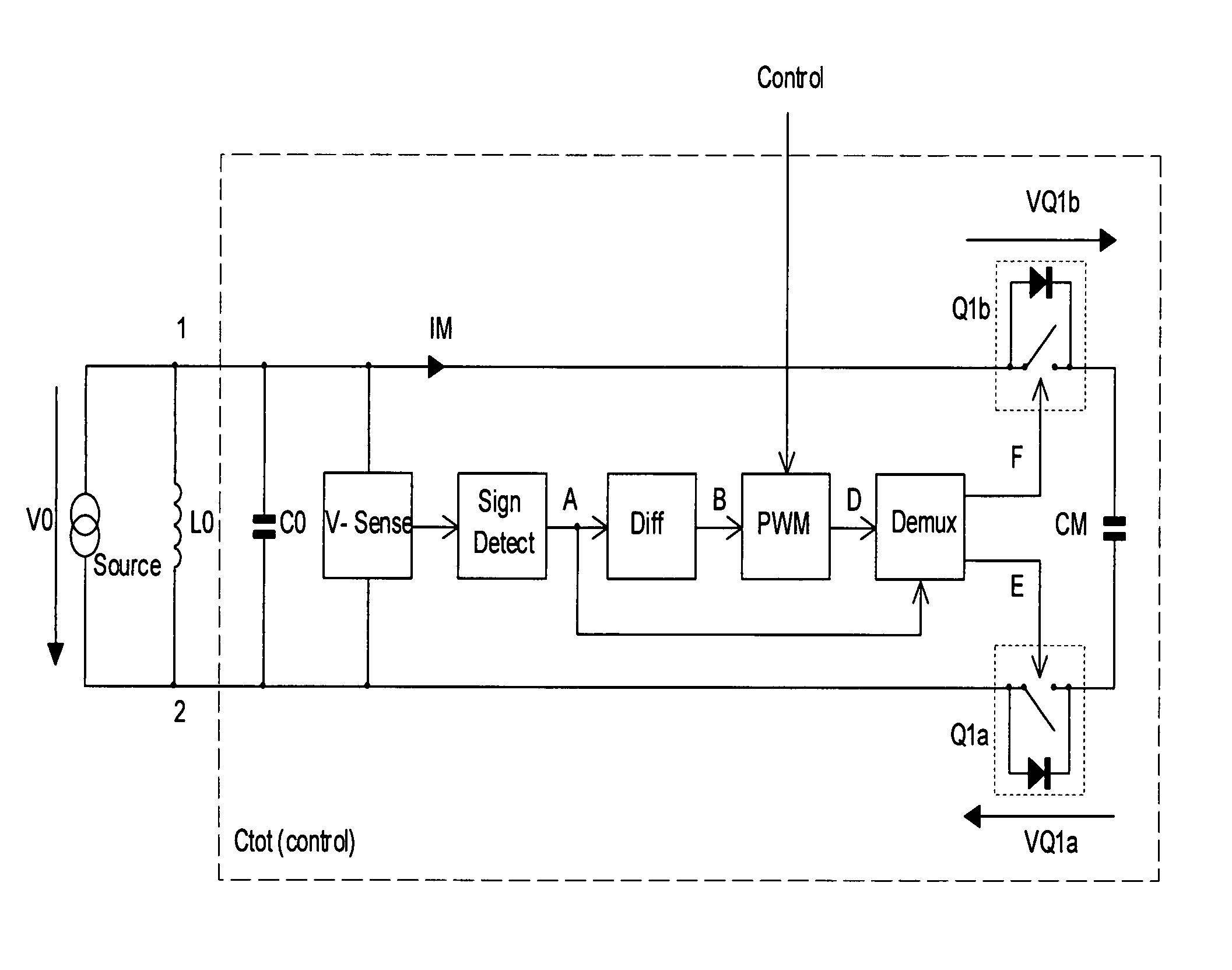
[0019]FIG. 3 shows the block diagram of a resonant network, whose total capacity is varied by an electrical input value. Signal waveforms of FIG. 3 are shown in FIG. 5 and are used in the further description with its indices. The energy source (source) is connected to the nodes 1 and 2 with a parallel resonant circuit. The energy source can be any AC power source or any part of a LC-coupled supply network (not shown). The inductor L0 and capacitor C0 form a resonant circuit. The capacitor CM is coupled to C0 via coupling switches Q1a and Q1b. The plotted diodes indicate that the coupling switches are controlled in only one direction. In the opposite current direction Q1a and Q1b remain bridged by the diodes. In the further description, the term switch defines the functional active controllable part of Q1a and Q1b. The term coupling switch defines the functional active controllable part and the diode. The first limiting conditions of the switch control is the one when the coupling sw...


PUM


Abstract

An electrical resonance network comprising a first capacitor and a first inductor whose resonance frequency can be tuned by means of a second capacitor and / or a second inductor. The resulting effective capacitor- or inductor value of a network period is controlled by a variable coupling respectively decoupling interval by means of at least one coupling switch. The coupling respectively decoupling interval is synchronized by a sign change of a current and / or voltage in the network.

Description

FIELD OF THE INVENTION[0001]The present invention relates to tunable inductors or capacitors of the AC power electronics and in particular to switched inductors or capacitors in resonance circuits.BACKGROUND OF THE INVENTION[0002]Realizing electronically adjustable inductors or capacitors in large-signal applications enables the design of tunable oscillators and filters in various applications, which have no alternatives until now. One is interested in a high efficiency, a stable reliable operation and in low implementation cost in such applications. The design of switched circuit concepts, that fulfill all these requirements and remain operational far into the high frequency range, is a real challenge. First, the basic physical network conditions shall be met. In addition, it is important to consider component properties, which influence the network characteristics significantly. Controlled reactances based on switched capacitors or switched inductors have low losses and are used i...

Claims


Application Information

Patent Timeline
Patent Type & Authority Patents(United States)
IPC IPC(8): H03B5/08H03K7/08H03K17/296H03J5/24H03K3/017H04N3/16H04N3/22H04N3/27
CPCH04N3/22H04N3/27H03J5/246H04N3/16H03H7/325H03K3/037H03L7/099
Inventor REHM, MARKUS
Owner REHM MARKUS
Why Eureka
Try Eureka