Timing lock detection apparatus and method for digital broadcasting receiver

a technology of digital broadcasting receiver and lock detection, which is applied in the direction of noise figure or signal-to-noise ratio measurement, transmission monitoring, pulse technique, etc., can solve the problems of extending the converging time, affecting the accuracy of the detection method, so as to reduce the complexity of hardware, prevent the detection of lock detection errors, and obtain the convergence properties quickly and accurately

Inactive Publication Date: 2011-04-26
ELECTRONICS & TELECOMM RES INST
View PDF12 Cites 4 Cited by
  • Summary
  • Abstract
  • Description
  • Claims
  • Application Information

AI Technical Summary

Benefits of technology

[0024]It is, therefore, an object of the present invention to provide to a timing lock detection apparatus and method for a digital broadcasting receiver, which reduces a hardware complexity, prevents a lock detection error, and quickly and accurately obtains convergence properties using a difference of timing error signals (ΔTiming_error) outputted from a loop filter of a symbol timing recovery unit to determine a converging level, that is a timing jitter signal.

Problems solved by technology

The conventional timing lock detector shown in FIG. 2A has problems in which the cost of hardware for variance calculation is very high, and a fixed threshold can generate a incorrect lock signal because a variance after convergence can vary according to a channel state, thereby occurring a lock detection error.
Such a lock detection error not only extends the converging time but also makes the convergence impossible for a large timing frequency and phase offset.
However, the conventional timing lock detector of FIG. 2B also has problems as follows.
The calculation of the average DC power value and the unit jitter power value requires high hardware cost as much as the calculation of variance in the timing lock detector in FIG. 2A.
That is, the conventional timing lock detector shown in FIG. 2B dose not have any improvement in a view of the hardware cost.
Therefore, the timing lock detector of FIG. 2B still has the problem of the timing lock detector of FIG. 2A.

Method used


Image

  • Timing lock detection apparatus and method for digital broadcasting receiver
  • Timing lock detection apparatus and method for digital broadcasting receiver
  • Timing lock detection apparatus and method for digital broadcasting receiver

Examples


Embodiment Construction

[0036]Hereinafter, a timing lock detection apparatus and method for a digital broadcasting receiver in accordance with an embodiment of the present invention will be described in more detail with reference to the accompanying drawings.

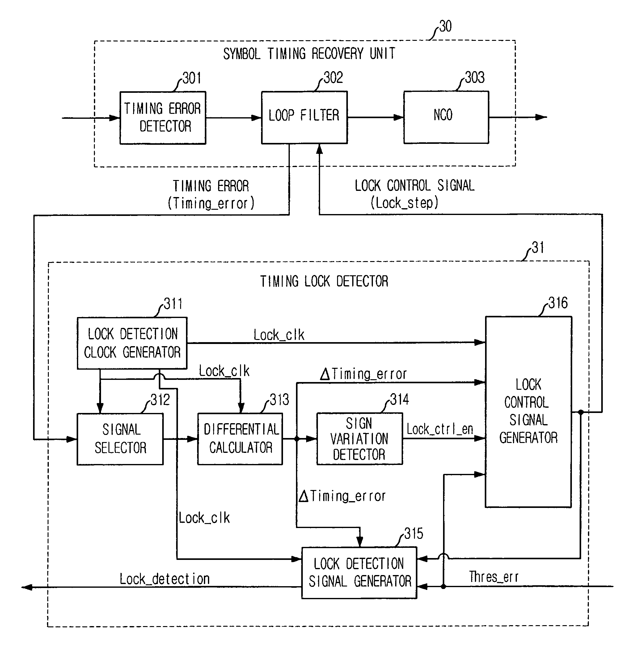
[0037]FIG. 3 is a block diagram illustrating a timing lock detection apparatus for a digital broadcasting receiver in accordance with en embodiment of the present invention.

[0038]Referring to FIG. 3, a timing recovery apparatus includes a symbol timing recovery unit 30 and a lock detection apparatus (or timing lock detector) 31. The symbol timing recovery unit 30 determines a timing recovery loop in a plurality of steps according to a converging level. The symbol timing recovery unit 30 includes a timing error detector 301, a loop filter 302 shown in FIG. 5, and an numerically controlled oscillator (NCO) 303. The lock detection apparatus 31 includes a lock detection clock generator 311, a signal selector 312, a differential calculator 313, a sign varia...


PUM


Abstract

A timing lock detection apparatus and method for digital broadcasting receiver are provided. The apparatus includes: a discrete value generator for cyclically selecting a discrete signal value from a continuous timing error signal; a differential calculator for obtaining a difference between the currently selected timing error signal value and a previously selected timing error signal that is a timing jitter signal; a sign variation detector for detecting variation in a sign of the timing jitter signal; a lock control signal generator for discriminating a period based on the detected sign changing time, and controlling a lock step of the loop filter according to a convergence mode of the timing jitter signal at each period; and a lock detection signal generator for generating a lock signal or an unlock signal according to whether the timing jitter signal reaches a steady state and using the current lock step signal.

Description

FIELD OF THE INVENTION[0001]The present invention relates to a timing lock detection apparatus and method for digital broadcasting receiver; and, more particularly, to a timing lock detection apparatus and method for a digital broadcasting receiver, which reduces abruptly hardware complexity, prevents a lock detection error, and quickly and accurately obtains convergence properties using a difference of timing error signals (ΔTiming_error) outputted from a loop filter of a symbol timing recovery unit to determine a converging level, that is a timing jitter signal.DESCRIPTION OF RELATED ARTS[0002]FIG. 1 is a block diagram illustrating a QAM demodulator including a convention timing lock detector.[0003]A quadrature amplitude modulation (QAM) is selected as a standard of a transmission method of a digital TV cable channel. A digital QAM demodulator employing such a QAM includes a numerically controlled oscillator (NCO) 101, a multiplier 102, a matched filter & re-sampler 103, a symbol ...

Claims


Application Information

Patent Timeline
Patent Type & Authority Patents(United States)
IPC IPC(8): H04B3/46
CPCH04B3/462H04L7/033H04H40/18H04L7/0004
Inventor JIN, EUN-SEOKKWON, O-HYUNGLEE, SOO-IN
Owner ELECTRONICS & TELECOMM RES INST
Why Eureka
Try Eureka