Method of joining tubular members

a tubular member and joint technology, applied in the field of tubular member forming, can solve the problems of dimensional distortion time-consuming joint corrosion, welding and bonding processes, etc., and achieve the effect of eliminating joint corrosion and dimensional distortion, and facilitating and fastening the assembly of the tubular member

Inactive Publication Date: 2005-08-02
GM GLOBAL TECH OPERATIONS LLC
View PDF19 Cites 22 Cited by
  • Summary
  • Abstract
  • Description
  • Claims
  • Application Information

AI Technical Summary

Benefits of technology

[0008]One advantage of the present invention is that a method of joining tubular members together to form a joint therebetween is provided for a vehicle, eliminating welding of the tubular members. Another advantage of the present invention is that the method allows a thermal interference fit tubular joint, to assemble hydroframe structures. Yet another advantage of the present invention is that the method allows easier and faster assembly of tubular members by eliminating welding and adhesive bonding. Still another advantage of the present invention is that the method eliminates joint corrosion and dimensional distortion caused by welding. A further advantage of the present invention is that the method allows dissimilar metals (e.g., aluminum to steel) to be assembled.
[0009]Other objects, features, and advantages of the present invention will be readily appreciated, as the same becomes better understood, after reading the subsequent description taken in conjunction with the accompanying drawings.

Problems solved by technology

However, these joints require welding and / or adhesive bonding.
During welding, dimensional distortion of the tubular members may occur, which is undesired.
In addition, the welding process may cause joint corrosion.
Further, only similar metals may be used in the welding process.
Additionally, the welding and bonding are time consuming processes for assembly.

Method used


Image

  • Method of joining tubular members
  • Method of joining tubular members
  • Method of joining tubular members

Examples


Embodiment Construction

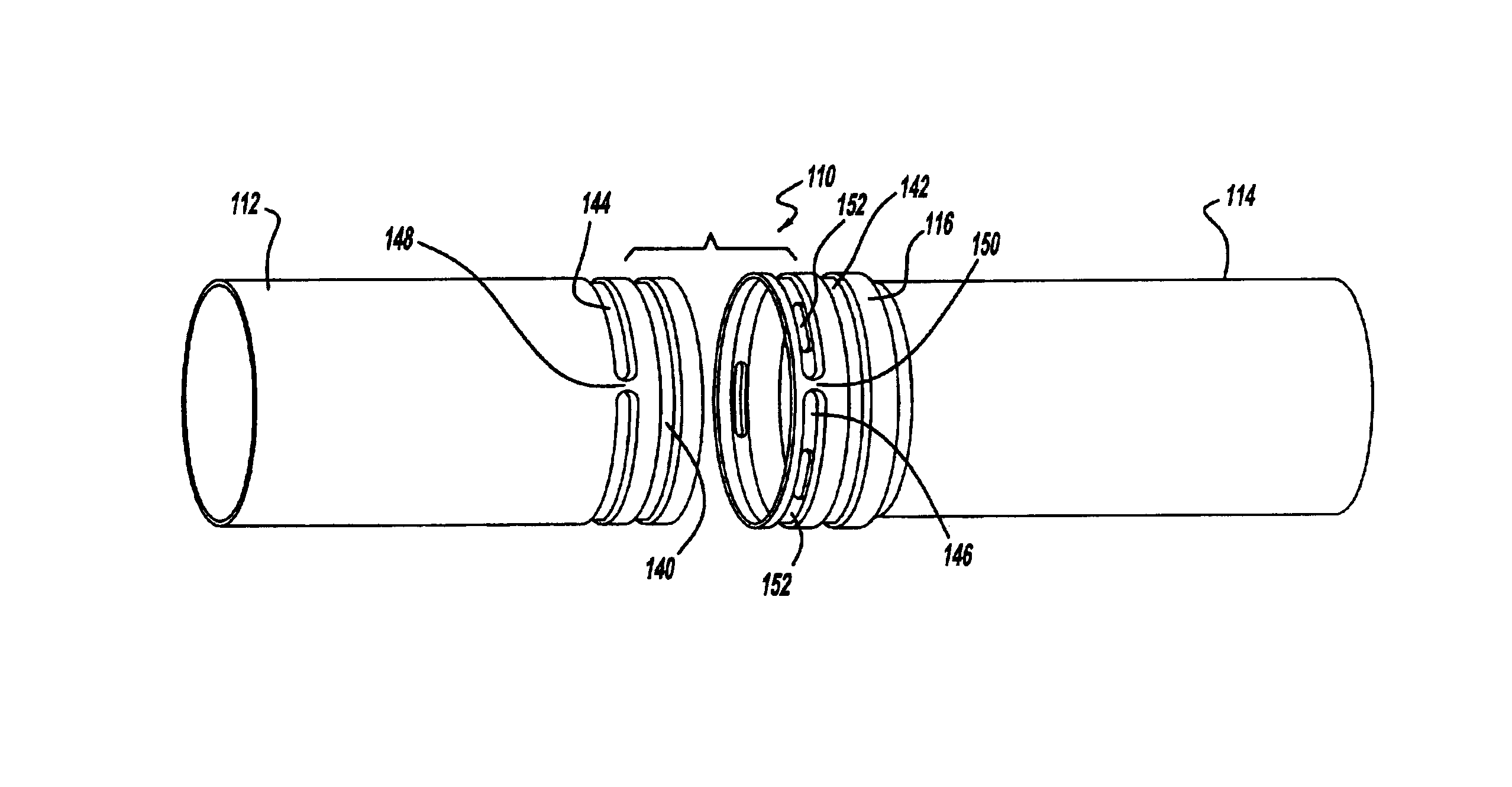
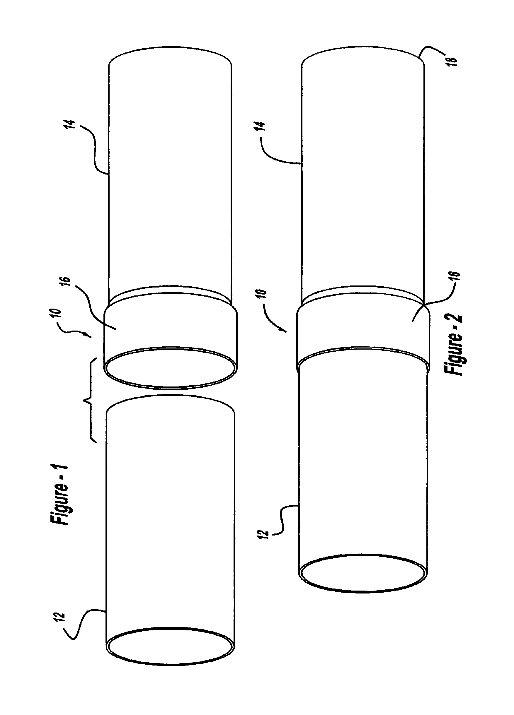
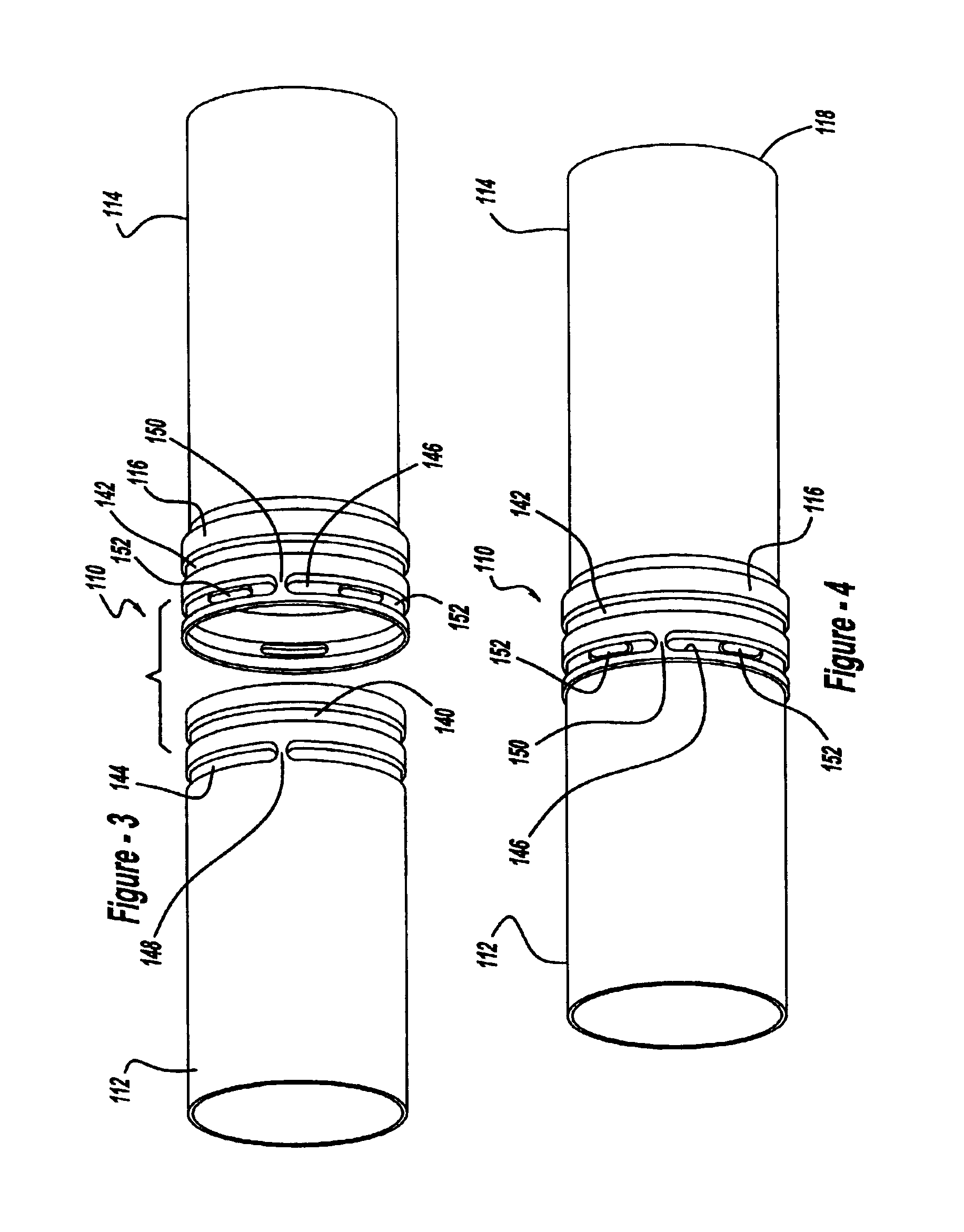
[0015]Referring to the drawings and in particular FIGS. 1 and 2, one embodiment of a joint 10, according to the present invention, for tubular blank or members 12 and 14 is shown for use in carrying out a method, according to the present invention, of joining the tubular members 12 and 14 with the joint 10 therebetween for assembly in automotive structures (not shown). The method includes the step of providing an internal tubular member 12 and an external tubular member 14. The internal and external tubular members 12 and 14 are made of a metal material. In one embodiment, the internal tubular member 12 has a generally circular cross-sectional shape and extends axially and the external tubular member 14 has a generally circular cross-sectional shape and extends axially. The external tubular member 14 has a flange or integral expansion or expanded region 16 at one end extending radially and axially to receive and overlap a portion of the internal tubular member 12 when the internal a...


PUM

PropertyMeasurementUnit
hydraulic pressureaaaaaaaaaa
internal hydraulic pressureaaaaaaaaaa
shapeaaaaaaaaaa

Abstract

A method of joining tubular members together includes the steps of providing an internal tubular member, providing an external tubular member, and heating the external tubular member and/or cooling the internal tubular member. The method also includes the steps of joining the internal tubular member and second tubular member together to form an overlap region of a joined tubular member, and positioning the joined tubular member between open die halves mating with one another to define a tubular cavity portion. The method includes the steps of progressively closing the die halves to progressively deform the joined tubular member within the tubular cavity portion. The method includes the steps of applying hydraulic pressure to expand and conform the joined tubular member to the tubular cavity portion. The method also includes the steps of separating the die halves and removing the expanded joined tubular member from the die.

Description

TECHNICAL FIELD[0001]The present invention relates generally to forming a shaped tubular member and, more particularly, to a method of joining tubular members of hydroformed metal tubing for assembling automotive structures.BACKGROUND OF THE INVENTION[0002]It is known to hydroform tubular components. Hydroformed tubular components are becoming increasingly popular in automotive body structural applications. During vehicle body manufacturing, methods for hydroforming relatively simple frame structures have been performed. One method for producing a frame structure includes the steps of pre-assembling an initial frame having a plurality of cylindrical metal tubes interconnected by the insertion of the ends of the cylindrical tubes onto mating pre-formed hollow metal nodal joints at substantially uniform circular interfaces. The method also includes the steps of securely joining the tubes and nodal joints by welding at the circular interfaces. The method includes the steps of placing t...

Claims


Application Information

Patent Timeline
Patent Type & Authority Patents(United States)
IPC IPC(8): B21D39/04
CPCB21D39/04Y10T29/49911Y10T29/49865Y10T29/49805
Inventor SHAH, SANJAY MAHASUKHLALLENDWAY, IV, JOSEPH M.BRUGGEMANN, CHARLES J.
Owner GM GLOBAL TECH OPERATIONS LLC
Why Eureka
Try Eureka