Regulated pressure supply for a variable-displacement reversible hydraulic motor

a hydraulic motor and variable displacement technology, applied in the direction of fluid couplings, servomotors, screws, etc., can solve the problems of undesirable conditions, energy in the aerodynamic spring must be dissipated in the hydraulic system, etc., and achieve the effect of high flow capability

Active Publication Date: 2005-08-02
MOOG INC
View PDF4 Cites 46 Cited by
  • Summary
  • Abstract
  • Description
  • Claims
  • Application Information

AI Technical Summary

Problems solved by technology

However, when the control surface is returned from such deflected position, the energy in the aerodynamic spring must be dissipated in the hydraulic system.
Both of these conditions are undesirable as contamination may be introduced into the pressure supply system, and the return line may cavitate.

Method used


Image

  • Regulated pressure supply for a variable-displacement reversible hydraulic motor
  • Regulated pressure supply for a variable-displacement reversible hydraulic motor
  • Regulated pressure supply for a variable-displacement reversible hydraulic motor

Examples


first embodiment (fig.1)

First Embodiment (FIG. 1)

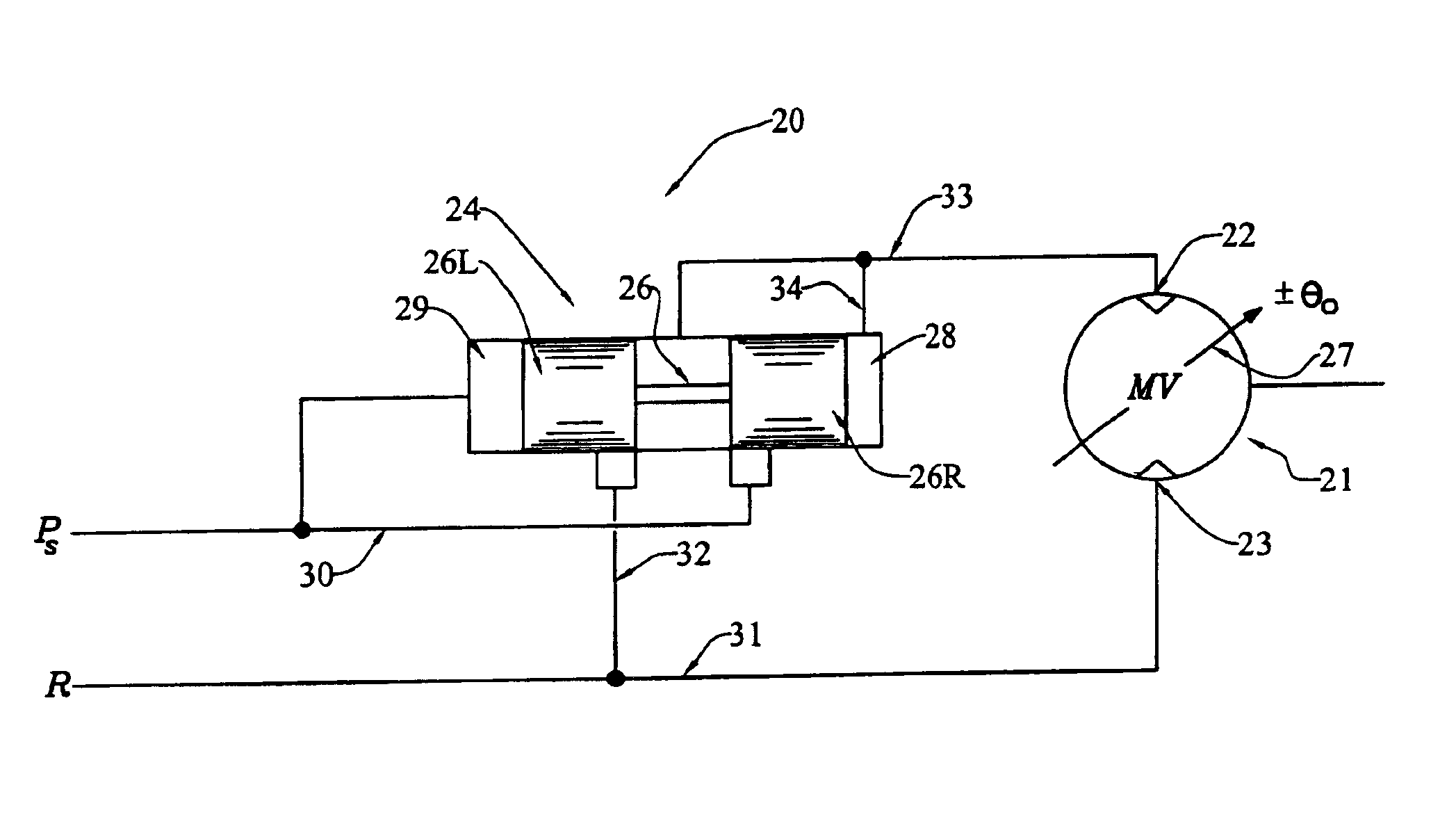
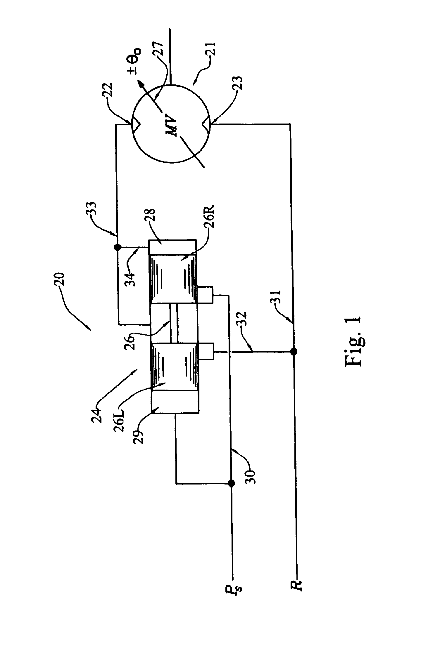
[0015]Referring now to FIG. 1, the present invention broadly provides an improved pressure-control device, of which a presently-preferred form is generally indicated at 20. Device 20 is shown as broadly including a controllable variable-displacement reversible hydraulic motor 21 having a pressure port 22 and a return port 23; a source of pressurized fluid Ps; a fluid return R; and a pressure regulating valve, generally indicated at 24.

[0016]The hydraulic motor may be of the type having a swashplate, schematically indicated by the symbol 27, the angle of which is controllable.

[0017]The pressure regulating valve 24 is shown as being a three-way valve having a two-lobed valve spool 26. The valve has a right spool end chamber 28 and a left spool end chamber 29. Pressurized fluid from the source is provided via line 30 to a port on the pressure regulating valve which is normally covered by the right spool lobe 26R. Another conduit 31 communicates the motor return...

second embodiment (fig.2)

Second Embodiment (FIG. 2)

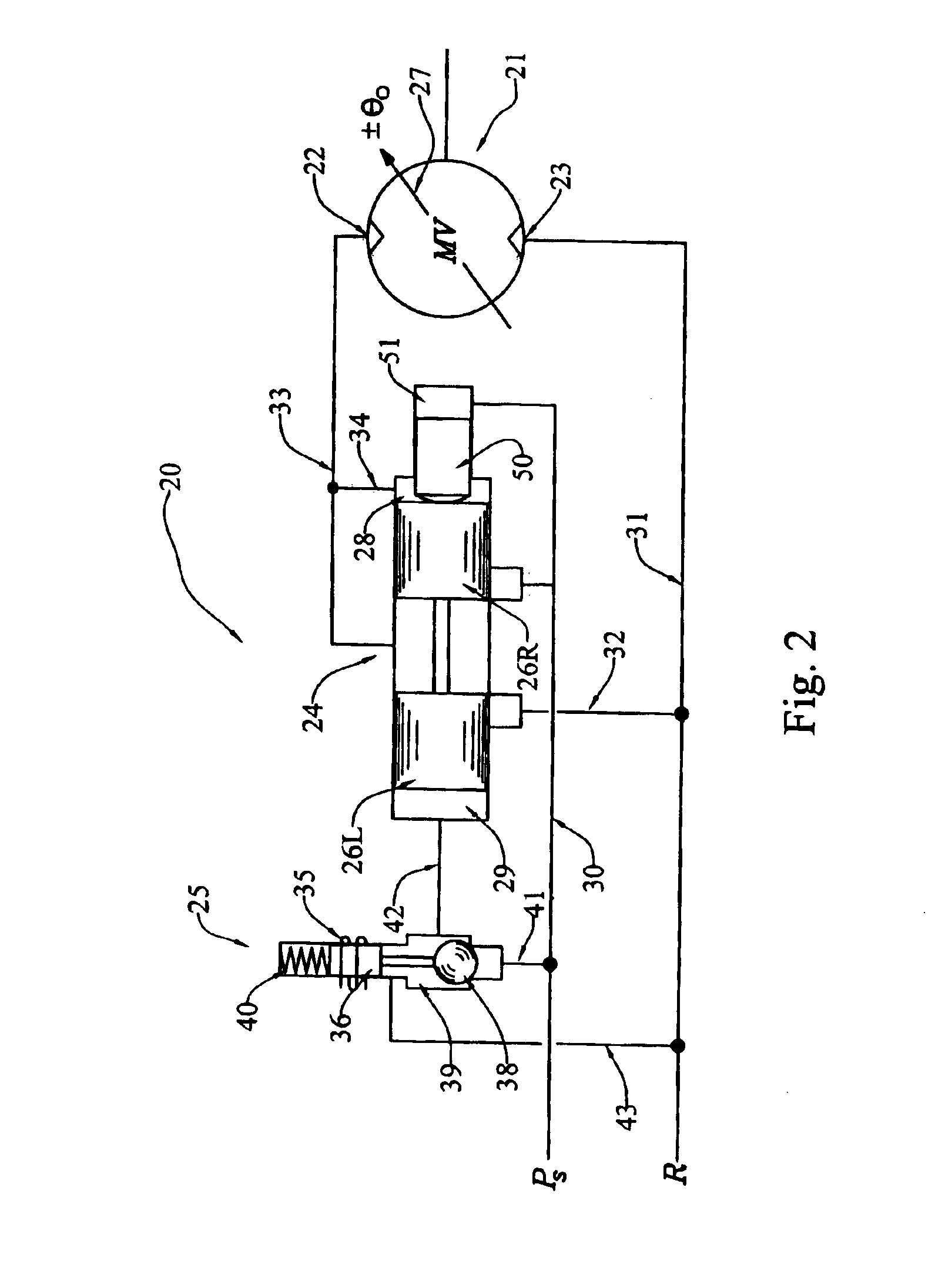
[0021]It is usually desirable to be able to positively disable a motor control system such as the one just described, and this typically requires a two-stage solenoid-operated high-flow pilot valve that removes pressure from the motor and provides a free-flow bypass to allow the motor to be back-driven. In a second form of the invention, the pressure regulating valve may be utilized in a shut-off / bypass mode by simply adding a solenoid pilot valve 25 to selectively control the reference pressure applied to the pressure regulating valve spool end chamber 29, as shown in FIG. 2.

[0022]The solenoid-operated pilot valve 25 is shown as having a coil 35, a plunger 36, a ball 38 arranged for movement within a chamber 39 for movement between two seats, and a spring 40 urging the plunger to move downwardly so as to prevent flow between conduits 41, 42. Branch conduit 41 communicates conduit 30 with the port below the ball, and branch conduit 42 communicates ball cham...


PUM


Abstract

A pressure-control device (20) includes a controllable variable-displacement reversible hydraulic motor (21) having a pressure port (22) and a return port (23); a source of pressurized fluid (Ps); a fluid return (R); and a pressure regulating valve (24) operatively interposed between the source, return and pressure port. The pressure regulating valve is operatively arranged to maintain a predetermined pressure at the pressure port regardless of the direction of flow through the pressure port.

Description

TECHNICAL FIELD[0001]The present invention relates generally to servomechanisms and components thereof, and, more particularly, to an improved regulated pressure supply for a variable-displacement reversible hydraulic motor.BACKGROUND ART[0002]Servo-controlled variable-displacement reversible hydraulic motors are frequently used to actuate secondary aircraft control surfaces, such as wing leading edge and trailing edge flaps, leading edge slats, door systems and the like, because of their hydraulic power efficiency. Such motors are typically connected to the aircraft's pressure supply line and to the return line. In such an arrangement, servocontrol of motor displacement determines the magnitude and direction of the motor output torque. These motors are typically supplied with a constant hydraulic supply pressure, and are controlled to produce a desired output torque by means of adjustment of a tiltable swashplate to change the motor displacement. In a reversible motor, the swashpla...

Claims


Application Information

Patent Timeline
Patent Type & Authority Patents(United States)
IPC IPC(8): B64C13/00B64C13/40F15B11/00F15B11/044
CPCB64C13/40F15B11/0445F15B2211/50536F15B2211/528F15B2211/55F15B2211/575F15B2211/7058F15B2211/76F15B11/08F15B11/00
Inventor POLCUCH, ERIC A.
Owner MOOG INC
Why Eureka
Try Eureka