Refrigeration cycle apparatus

a technology of refrigerant cycle and apparatus, which is applied in the direction of refrigeration components, liquefaction, lighting and heating apparatus, etc., can solve the problems of not being able to properly control the amount of refrigerant circulating in the refrigerant cycle, lowering the efficiency of the refrigeration cycle apparatus, and reducing the efficiency of the refrigeration cycle. achieve the effect of increasing the efficiency of the refrigerant cycle apparatus and increasing the amount of energy recovery

Inactive Publication Date: 2005-08-02
HITACHI AIR CONDITIONING SYST
View PDF12 Cites 25 Cited by
  • Summary
  • Abstract
  • Description
  • Claims
  • Application Information

AI Technical Summary

Benefits of technology

[0056]As mentioned above, since the structure is made such that two valves respectively provided in two flow passages taking in and out the refrigerant with respect to the refrigerant tank are opened and closed or controlled in the opening ratio on the basis of the detected temperature and pressure, it is possible to change a total amount of the refrigerant circulating in the refrigerant cycle, and it is possible to control the discharge pressure of the compressor in such a manner that the efficiency of the refrigerant cycle apparatus becomes highest.
[0057]In this case, in the structure mentioned above, the structure may ...

Problems solved by technology

In the prior arts mentioned above, since the expander and the compressor are integrally formed, a heat leak from the compressor to the expander is large, so that there is a defect that an efficiency of the refrigeration cycle apparatus is lowered.
Further, in both of the cooling operation and the heating operation in the refrigeration cycle apparatus, it is not considered to keep a pressure difference between the inlet an...

Method used


Image

  • Refrigeration cycle apparatus
  • Refrigeration cycle apparatus
  • Refrigeration cycle apparatus

Examples


Embodiment Construction

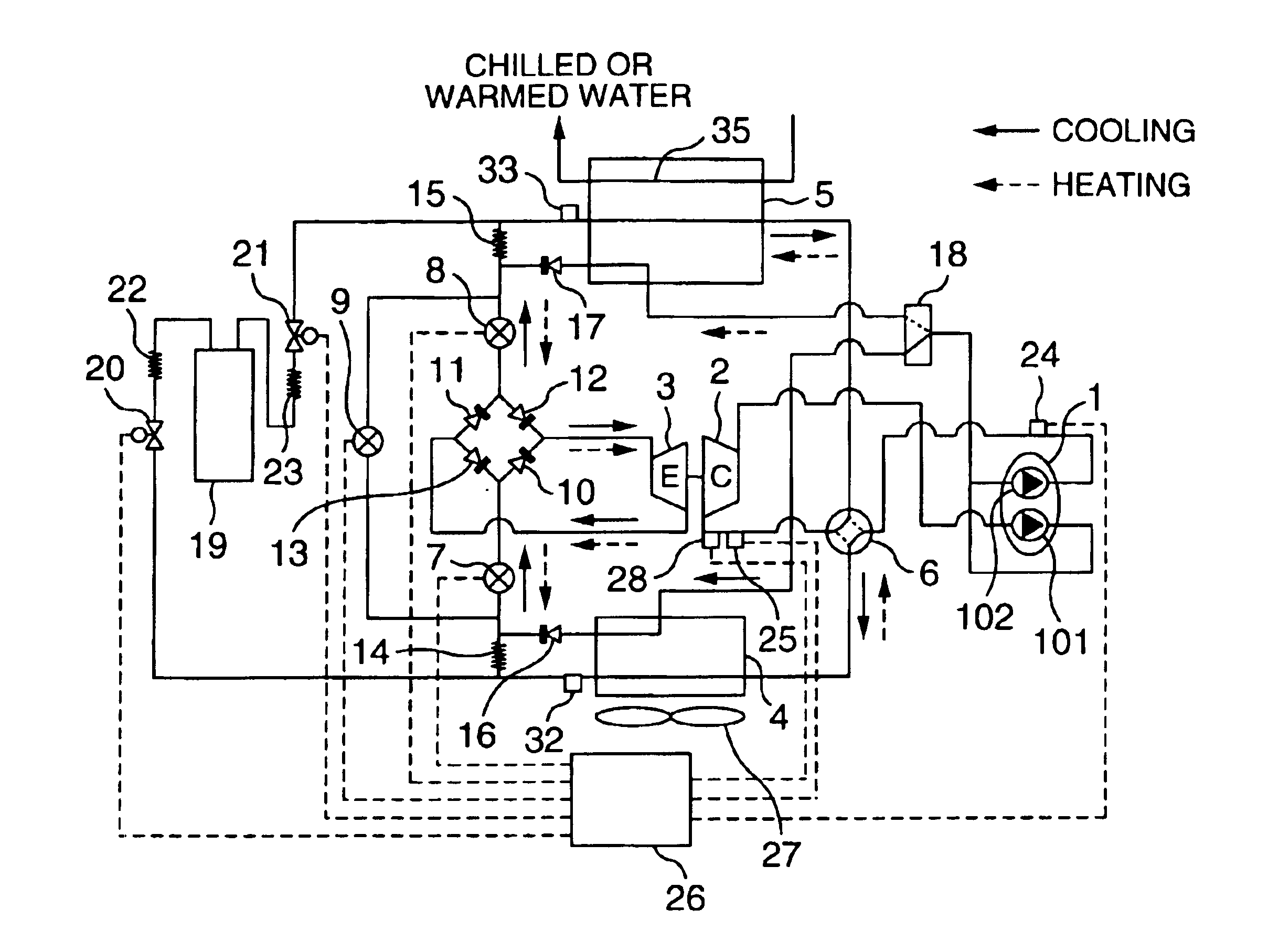
[0065]A description will be given below of a specific embodiment in accordance with the present invention with reference to the accompanying drawings. A description will be given of a first embodiment in accordance with the present invention on the basis of a refrigeration cycle structure view in FIG. 1. First, a description will be given of a flow and an operation of a refrigerant at a time of a cooling operation (in the case that a use side heat exchanger 5 is a cooler). In FIG. 1, the flow of the refrigerant at a time of the cooling operation is shown by a solid arrow. A main compressor (a first compressor) 1 is constituted by a two-stage compressor, for example, a 2-cylinder rotary compressor. A refrigerant under an intermediate pressure which is compressed by a first stage compression portion 101 of the main compressor partly flows to a second stage compression portion 102, and the rest thereof flows to a three-way valve (a refrigerant path changing means) 18, flows from the th...


PUM


Abstract

In a refrigerant cycle apparatus, an energy-saving operation is performed by using a refrigerant which is used in a supercritical state. A refrigeration cycle apparatus is constituted by a main compressor, an expander, a sub compressor independently placed in an upstream side of the main compressor, a use side heat exchanger, a heat source side heat exchanger and the like. A refrigerant such as a carbon dioxide or the like which is used in a supercritical state is employed as the refrigerant. The sub compressor is driven by utilizing a recovered energy by the expanding device. Further, a refrigerant tank is provided, and properly controls an amount of the refrigerant circulating in the refrigerant cycle.

Description

BACKGROUND OF THE INVENTION[0001]1. Field of the Invention[0002]The present invention relates to a refrigeration cycle apparatus provided with a compressor, a use side heat exchanger, a heat source side heat exchanger and an expander, and more particularly to a refrigeration cycle apparatus in which carbon dioxide is employed as a refrigerant constituting a refrigeration cycle.[0003]2. Description of Prior Art[0004]As the refrigeration cycle apparatus provided with the expander, there are, for example, structures described in JP-A-2002-22298 (patent document 1) and JP-A-2001-66006 (patent document 2). In the structure described in the patent document 1, an energy recovered by the expander is used as an auxiliary power of the compressor. Further, in the structure described in the patent document 2, a direction of the refrigerant flowing through the expander is fixed in both of a cooling operation and a heating operation.[0005]In the prior arts mentioned above, since the expander and ...

Claims


Application Information

Patent Timeline
IPC IPC(8): F25B9/06F25B1/10F25B13/00F25B9/00F25B49/02F25B41/04F25B45/00
CPCF25B1/10F25B9/008F25B9/06F25B13/00F25B41/046F25B45/00F25B49/02F25B2309/061F25B2313/0272F25B2400/13F25B2400/16F25B2600/17F25B2600/2523F25B2700/1931F25B2700/1933F25B2700/21151
Inventor FUNAKOSHI, SUNAOKOHSOKABE, HIROKATSUENDOH, KAZUHIROTOJO, KENJIMATSUSHIMA, HIROAKI
Owner HITACHI AIR CONDITIONING SYST
Why Eureka
Try Eureka