Microscale out-of-plane anemometer

a micro-scale, out-of-plane technology, applied in the field of sensing, can solve the problems of uneven performance, delicate fabrication process, and significant shortcomings of conventional hot-wire anemometers

Inactive Publication Date: 2005-08-02
THE BOARD OF TRUSTEES OF THE UNIV OF ILLINOIS
View PDF7 Cites 31 Cited by
  • Summary
  • Abstract
  • Description
  • Claims
  • Application Information

AI Technical Summary

Problems solved by technology

However, conventional hot-wire anemometers suffer from significant shortcomings.
One such shortcoming is that the fabrication process is delicate and may not result in uniform performance.
Another problem is that it may be prohibitively difficult to form large arrays of the anemometers for measuring flow distribution, for example.
However, bulk micromachining incurs significant cost and restricts the type of substrate that can be used.
For example, the doping of silicon (to create the resistive heater, for example), the etching of the silicon, and the packaging of individual silicon dies require significant expertise and effort.
Additionally, most micromachined hot-wire anemometers cannot be realized effectively in a large array format.
Furthermore, bulk micromachining requires significant etching time, and bulk etching using anisotropic wet etchants frequently poses concerns of materials compatibility, as all materials on a given substrate are required to sustain wet etching for long periods (several hours to etch through typical silicon wafers, for example).
However, polysilicon deposition and annealing require a high-temperature process and generally preclude the use of substrates with a low melting point.
This leads to a slower frequency response and reduced sensitivity.

Method used


Image

  • Microscale out-of-plane anemometer
  • Microscale out-of-plane anemometer
  • Microscale out-of-plane anemometer

Examples


Embodiment Construction

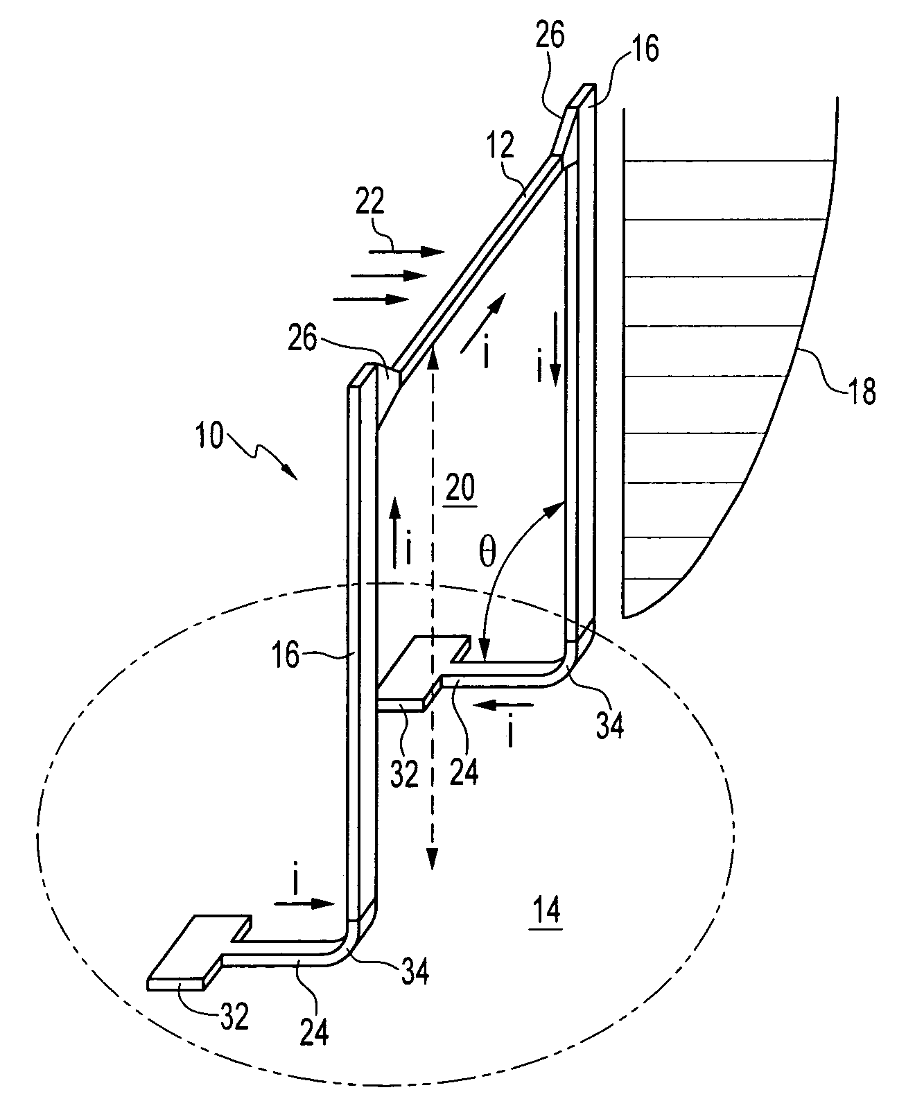
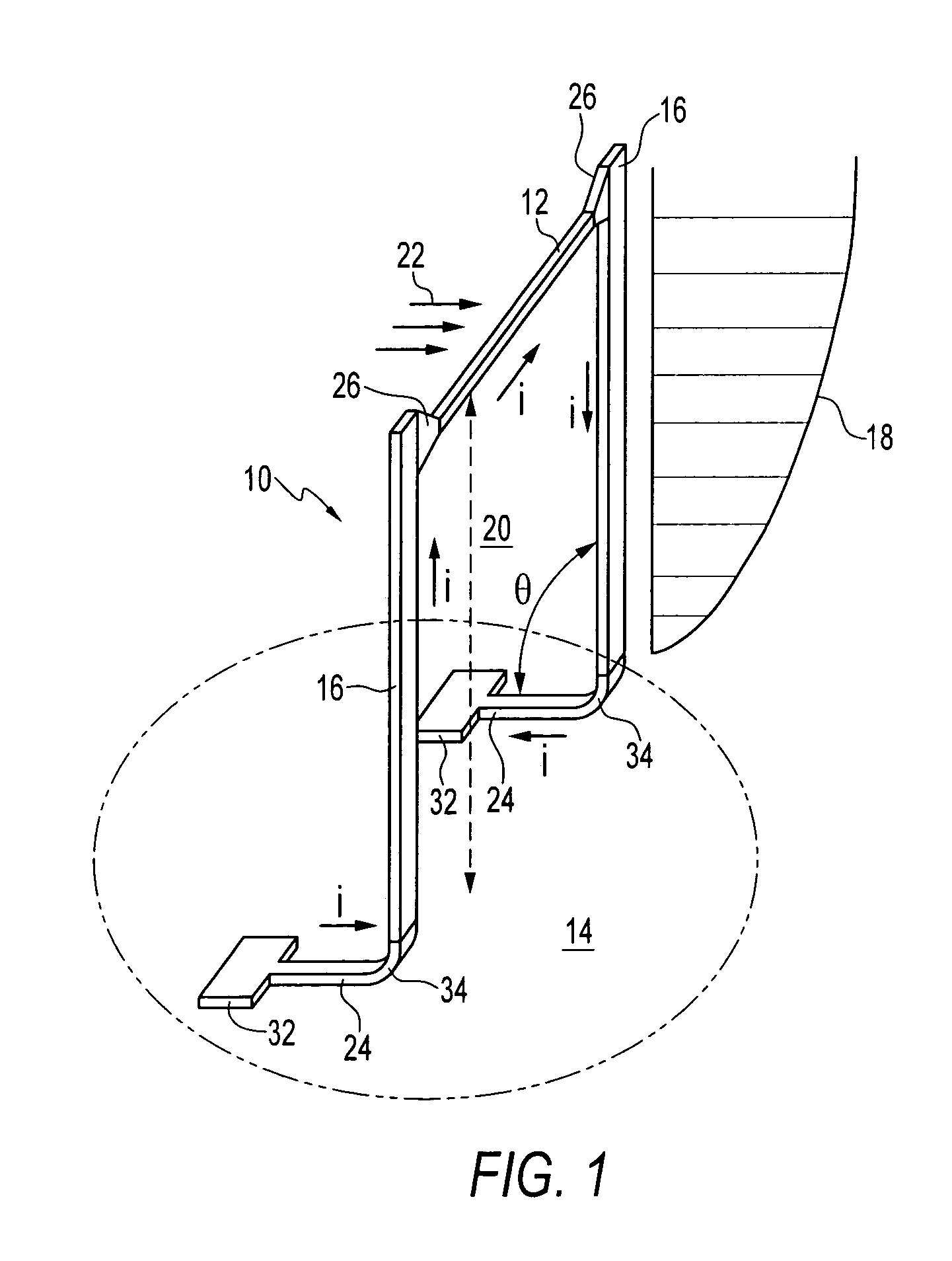
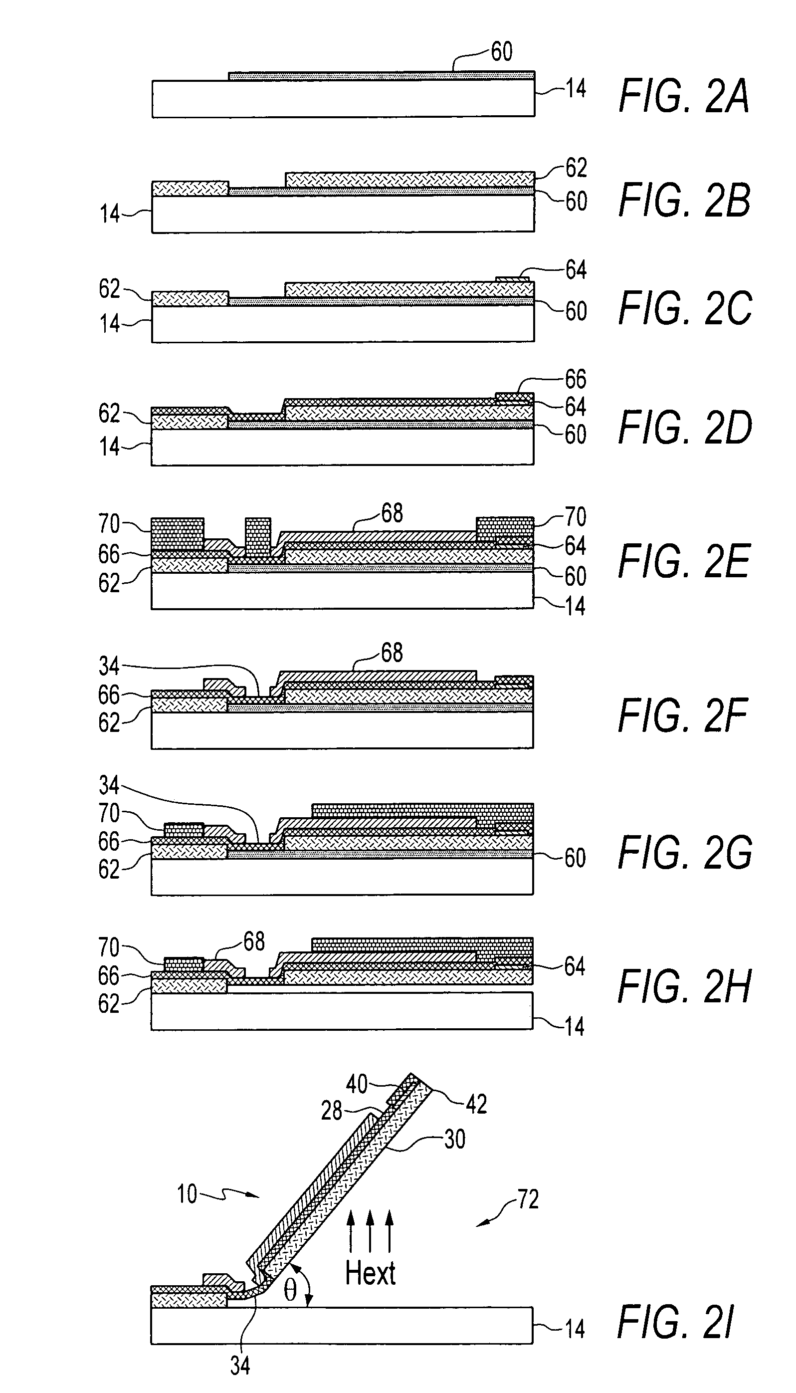
[0024]The present invention provides, among other things, a microscale thermal sensor produced on a substrate by surface micromachining. The thermal sensor provided on a substrate includes a resistive heater, preferably containing a thin film, suspended above the substrate by supports attached at one end to the substrate, either directly or indirectly. The thin film is produced from temperature-sensitive, electrically conductive material. As opposed to conventional microscale anemometers, the present thermal sensor allows non-silicon materials to be used for the resistive heater and / or the substrate. Furthermore, it is preferred that the resistive heater including the thin film be made of a non-silicon material, such as a metal.

[0025]The supports are raised at an angle with respect to the substrate to suspend the resistive heater, preferably creating a clearance underneath the resistive heater for flow of a fluid media. The clearance may be defined, for example, by the resistive hea...


PUM

PropertyMeasurementUnit
lengthaaaaaaaaaa
lengthaaaaaaaaaa
temperatureaaaaaaaaaa

Abstract

A microscale out-of-plane thermal sensor. A resistive heater is suspended over a substrate by supports raised with respect to the substrate to provide a clearance underneath the resistive heater for fluid flow. A preferred fabrication process for the thermal sensor uses surface micromachining and a three-dimensional assembly to raise the supports and lift the resistive heater over the substrate.

Description

PRIORITY CLAIM[0001]This application claims priority of U.S. Provisional Application Ser. No. 60 / 349,431, filed Jan. 18, 2002 under 35 U.S.C. § 119.STATEMENT OF GOVERNMENT INTEREST[0002]This invention was made with Government assistance under National Science Foundation Grant No. NSF IIS 99-84954, National Aeronautics and Space Administration Grant No. NASA NAG 5-8781, and National Science Foundation Grant No. NSF IIS-0080639. The Government has certain rights in the invention.FIELD OF THE INVENTION[0003]A field of the invention is sensing. Other fields of the invention include microelectronics and micro-electromechanical systems.BACKGROUND OF THE INVENTION[0004]Measuring fluid flow velocity is useful for turbulence flow measurement in fluid mechanics research, and any industrial application where flow measurement is required, such as, but not limited to, gas metering and air duct monitoring. Commercial flow sensors are mainly based on one of two principles: thermal anemometry and l...

Claims


Application Information

Patent Timeline
Patent Type & Authority Patents(United States)
IPC IPC(8): G01F1/684G01P5/10G01P5/12G01F1/688
CPCG01F1/6845G01F1/688G01P5/12Y10T29/49083Y10T29/49007Y10T29/49002Y10T29/49004
Inventor LIU, CHANGCHEN, JACK
Owner THE BOARD OF TRUSTEES OF THE UNIV OF ILLINOIS
Why Eureka
Try Eureka