
Throttle device for internal combustion engine

a technology of internal combustion engine and throttle valve, which is applied in the direction of engine controllers, machines/engines, valve arrangements, etc., can solve the problems of inability to control normal idling speed of the internal combustion engine, and inability to stop the throttle valve, so as to prevent the entry of foreign matter, prevent the leakage of air, and the effect of superior sliding

Inactive Publication Date: 2005-08-02
DENSO CORP
View PDF6 Cites 22 Cited by
  • Summary
  • Abstract
  • Description
  • Claims
  • Application Information

AI Technical Summary

Benefits of technology

The present invention provides a throttle device for an internal combustion engine that can improve the precision of assembly and reduce the number of assembly steps. It also reduces leakage when the throttle valve is fully closed and prevents abnormal wear of the bearing. The throttle device includes a throttle shaft, a throttle body, and an integral plug-type slide bearing. The bearing support of the throttle body has a shaft insertion hole in which the sliding part of the throttle shaft is inserted and a ring-shaped end face that faces the outside from the center of the bore wall in the axial direction of the throttle shaft. The flange of the integrated plug-type slide bearing is fixed by welding to the ring-shaped end face of the bearing support. This allows for optimal assembly of the plastic integrated plug-type slide bearing in a non-machined plastic throttle body.

Problems solved by technology

Due to this, the idling speed of the internal combustion engine will become higher than the target value, so the problem will arise of the inability of normal idling control.
If moving the full close position of the throttle valve too much to the closing side so as to solve this problem, that is, to reduce the amount of leakage when the valve is fully closed, before the rotational motion of the throttle valve is stopped by the full close stopper etc. at the full close position, the outer circumference of the disk of the throttle valve will interfere with the inner circumference of the bore wall of the throttle body and lock and therefore the problem will arise of the inability to stop the throttle valve at a predetermined full close position.
Due to this, if the sliding part of the throttle shaft sticks or other problems arise, the valve will lock and the opening degree of the throttle valve will no longer be able to be controlled.
Further, if forming the throttle body and the throttle valve integrally by plastic, the dimensional precision or parts precision will become poorer due to molding shrinkage etc. compared with machined parts, so the problem will arise of the precision of assembly becoming very poor if press fitting the outer circumference of the tube of the integral plug-type slide bearing in the inner circumference of the bearing support of the throttle body.

Method used


Image

  • Throttle device for internal combustion engine
  • Throttle device for internal combustion engine
  • Throttle device for internal combustion engine

Examples


first embodiment

[0034

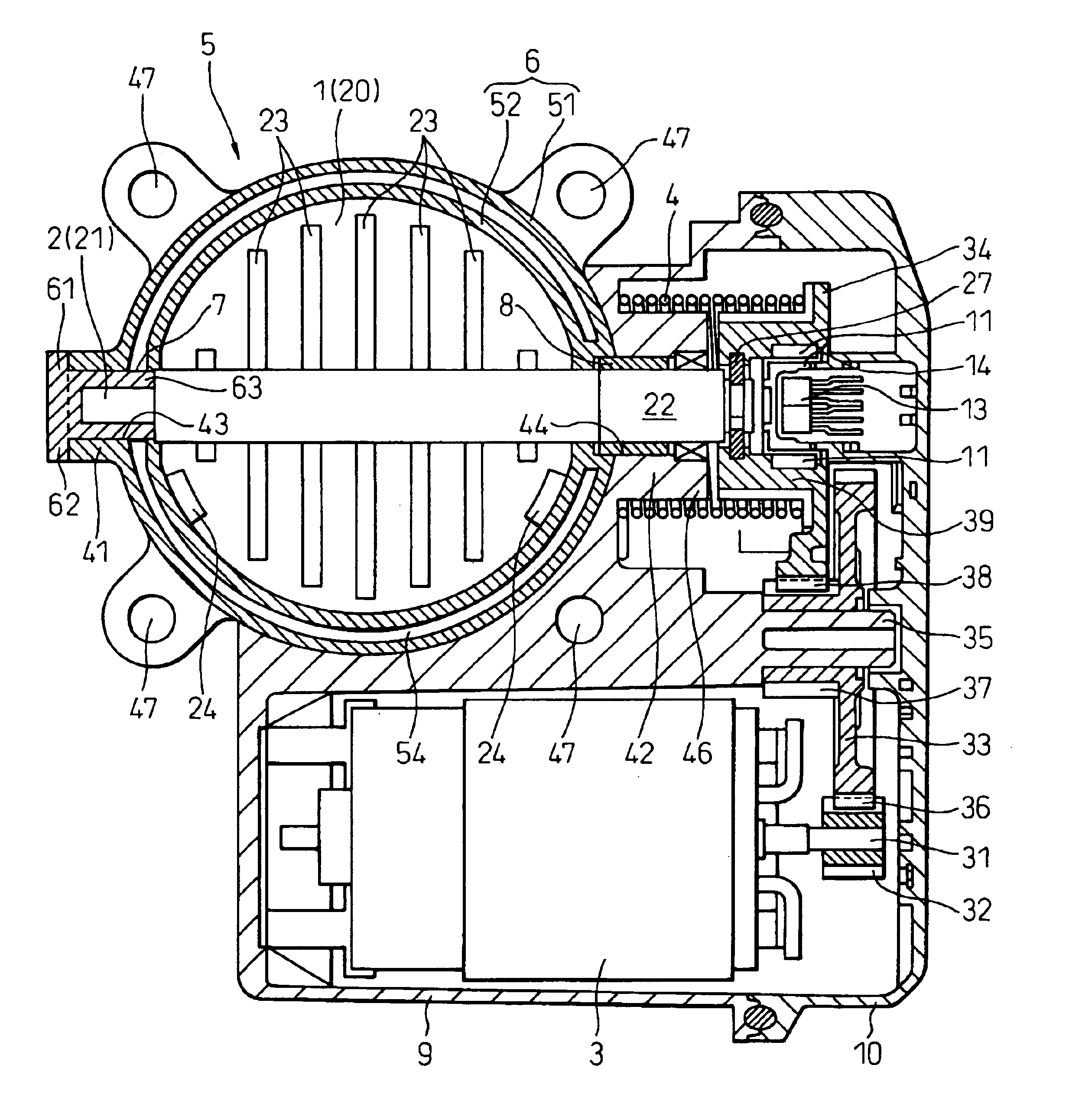
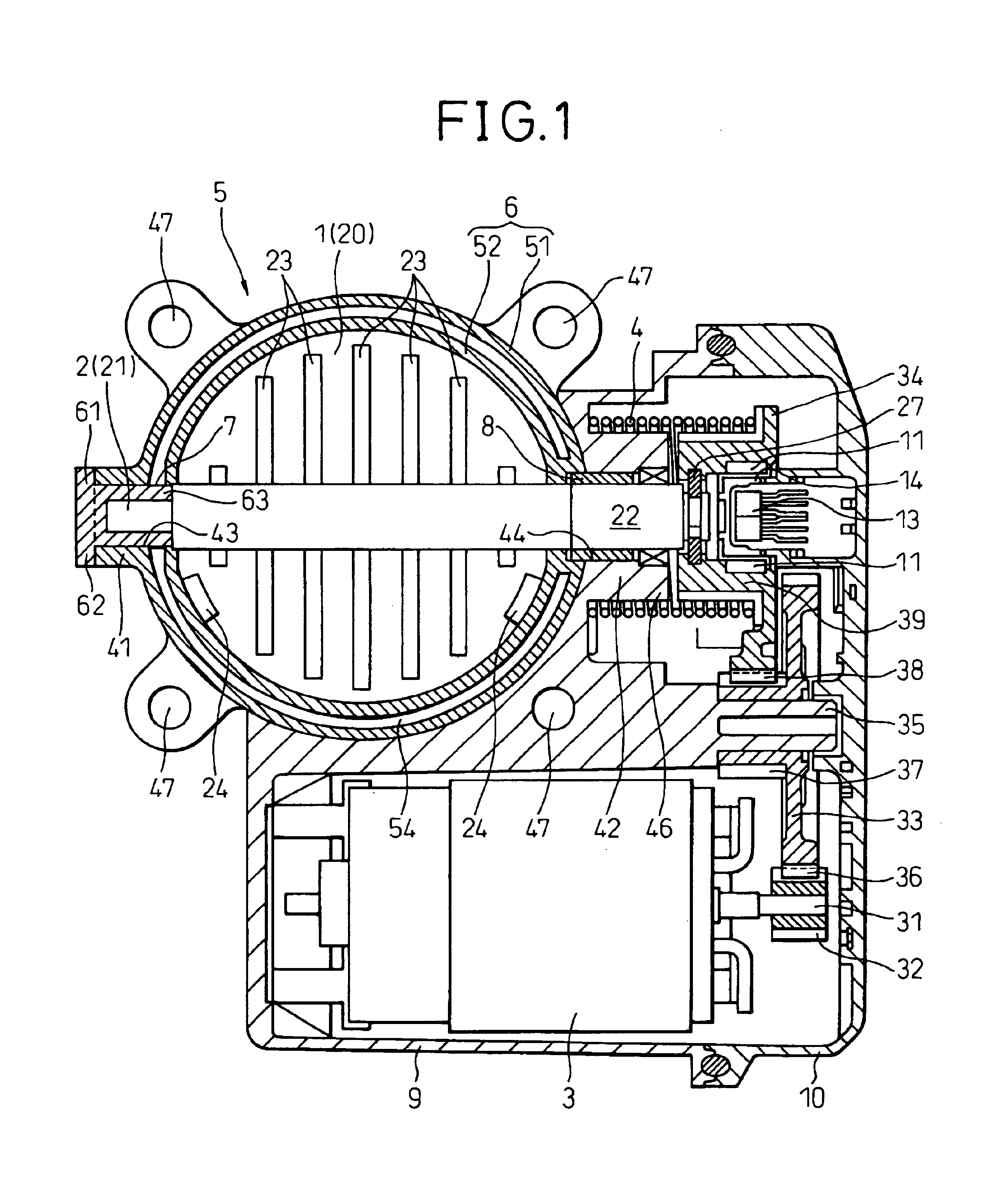
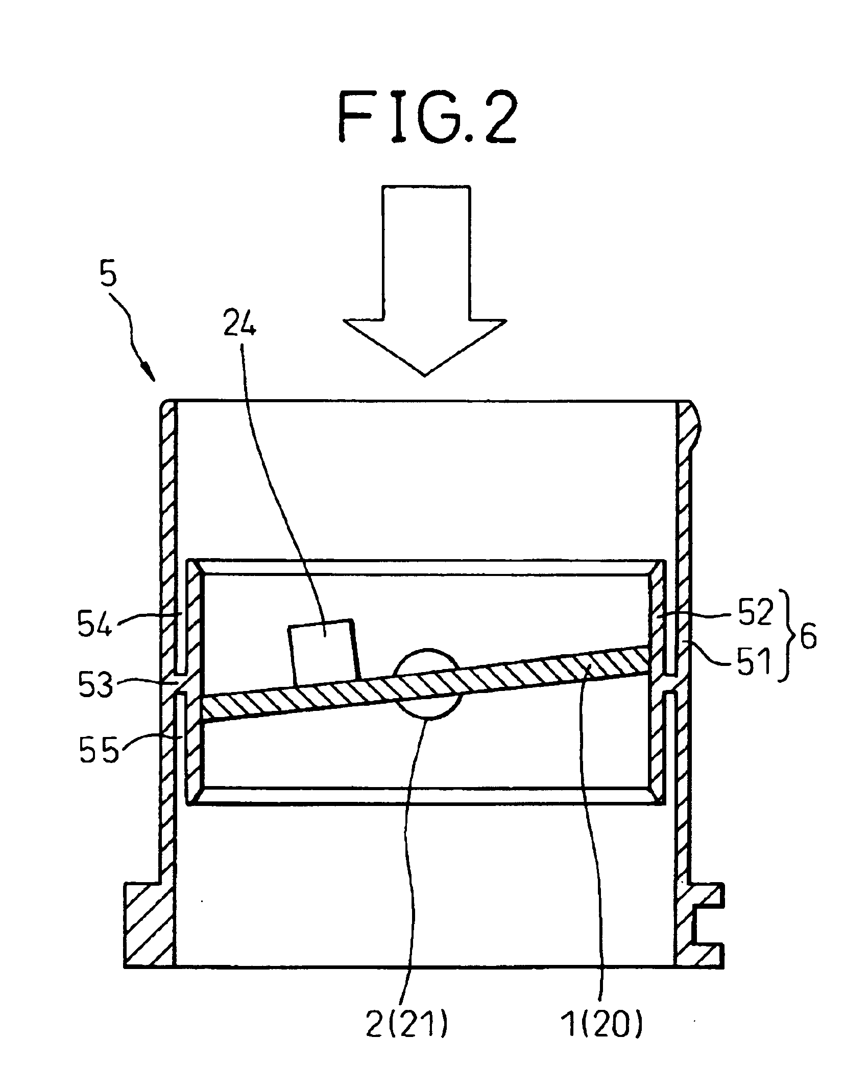
[0035]FIG. 1 and FIG. 2 show a first embodiment of the present invention. FIG. 1 is a view of the overall structure of an electronic control type throttle control device, while FIG. 2 is a view of the structure of the bore wall of the throttle body.

[0036]The electronic control type throttle control device of the present embodiment is an intake control device of an internal combustion engine provided with a throttle valve 1 for controlling the amount of intake air of the internal combustion engine (hereinafter called simply an “engine”), a throttle shaft 2 forming a shaft part of the throttle valve 1, a drive motor 3 for driving the throttle valve 1 and the throttle shaft 2 in the full open direction (or full closed direction), a coil spring or other return spring (valve biasing means) 4 for biasing the throttle valve 1 and the throttle shaft 2 in the full closed direction, a reduction gear (power transmission) for transmitting rotational output of the drive motor 3 to the throt...

second embodiment

[0080

[0081]FIG. 3 shows a second embodiment of the present invention and illustrates only the main structure of an electronic control type throttle control device.

[0082]In the second embodiment, the first bearing support 41 of the throttle body 5 is provided with a single communication hole 64 communicating the outer circumference and inner circumference or two or more holes at predetermined intervals (for example, at equal intervals in the circumferential direction). The communication holes 64 are used as gates for pouring a molten plastic into the circumferential direction ring-shaped clearance formed between the outer circumference of the closed bottom tube 63 of the integral plug-type slide bearing 7 and the first shaft insertion hole 43 of the first shaft bearing 41 of the throttle body 5. Further, the tube 63 of the slide bearing 7 is fixed by welding to the first bearing support 41 of the throttle body 5 through the plastic material 65 poured from the communication holes 64.

[...


PUM


Abstract

A throttle device for an internal combustion engine designed to absorb variations in dimensions of components by centering a closed-bottom tube of an integral plug-type slide bearing with a plastic shaft part of a throttle shaft, inserting a tube of the slide bearing in a ring-shaped clearance formed between an inner circumference of a first shaft insertion hole of a first bearing support of a throttle body and outer circumference of a first sliding part of the plastic shaft, then fixing by welding a ring-shaped end face of a flange of the slide bearing to a ring-shaped end face of the first bearing support using a welding method such as laser welding.

Description

BACKGROUND OF THE INVENTION[0001]1. Field of the Invention[0002]The present invention relates to a throttle device for an internal combustion engine, more particularly relates to a bearing structure of an electronic control type throttle control device for controlling an opening degree of a throttle valve in accordance with an amount of operation of a throttle by a drive motor or other actuator.[0003]2. Description of the Related Art[0004]As shown in FIG. 4, in the related art, there has been proposed a throttle device for an internal combustion engine provided with a throttle valve for controlling an amount of intake air to the internal combustion engine, a throttle shaft 102 forming a shaft part of the throttle valve 101, a throttle body 104 operably holding the throttle valve 101 in a tubular shaped bore wall 103, a slide bearing 107 press fit inside a first bearing support 105 provided so as to stick out to one side from the outer circumference of the bore wall 103 and rotatably...

Claims


Application Information

Patent Timeline
Patent Type & Authority Patents(United States)
IPC IPC(8): F02D9/10F02D9/08F16K1/22
CPCF02D9/104F02D9/1065F16K1/22F16K1/225
Inventor TORII, KATSUYASHIMADA, HIROKI
Owner DENSO CORP
Learn More