Fuel injection timer and current regulator

a current regulator and fuel injection technology, applied in the direction of relays, machines/engines, electric control, etc., can solve the problems of adding complexity to the fuel injection system, difficult to maintain precise timing over the activation of the fuel injector, and high cost of voltage regulators, so as to achieve simple and economical control of the fuel injection system

Inactive Publication Date: 2005-08-02
VITESCO TECH USA LLC
View PDF10 Cites 6 Cited by
  • Summary
  • Abstract
  • Description
  • Claims
  • Application Information

AI Technical Summary

Benefits of technology

[0009]In another embodiment, an actual ramp time for a given injection is measured and used to predict future ramp times. This embodiment takes the actual operation of the entire injector into account, not just the applied voltage, and can compensate for changes in the coil inductance as well as voltage fluctuations.
[0010]By eliminating the need for a regulated voltage supply and operating the fuel injector based on an estimated or predicted ramp time, the invention can time fuel injection precisely without requiring a voltage regulator, providing a simple and economical way to control fuel injection.
[0011]The invention is also directed to a method and system for controlling injector current. The voltage source that powers the fuel injector can be controlled by monitoring current flow in the injector. In a current regulator according to one embodiment of the invention, the current is regulated by selectively connecting the fuel injector with one of two possible voltage sources. This provides injector current regulation without having to turn a voltage source on and off (chopping).

Problems solved by technology

The coils in fuel injectors tend to have a large amount of inductance, causing a delay between the time voltage is applied to the coil and the time that the coil has sufficient current flow (e.g., 20 A) to actually begin fuel injection.
These changes can cause the load current to open the valve at a time other than an expected time calculated from the nominal voltage, making it difficult to maintain precise timing over fuel injector activation.
Variations in the coil inductance also makes precise timing of fuel injection difficult.
Although voltage regulators can be used to stabilize the voltage applied to the coil, voltage regulators are expensive and add complexity to the fuel injection system.

Method used


Image

  • Fuel injection timer and current regulator
  • Fuel injection timer and current regulator
  • Fuel injection timer and current regulator

Examples


Embodiment Construction

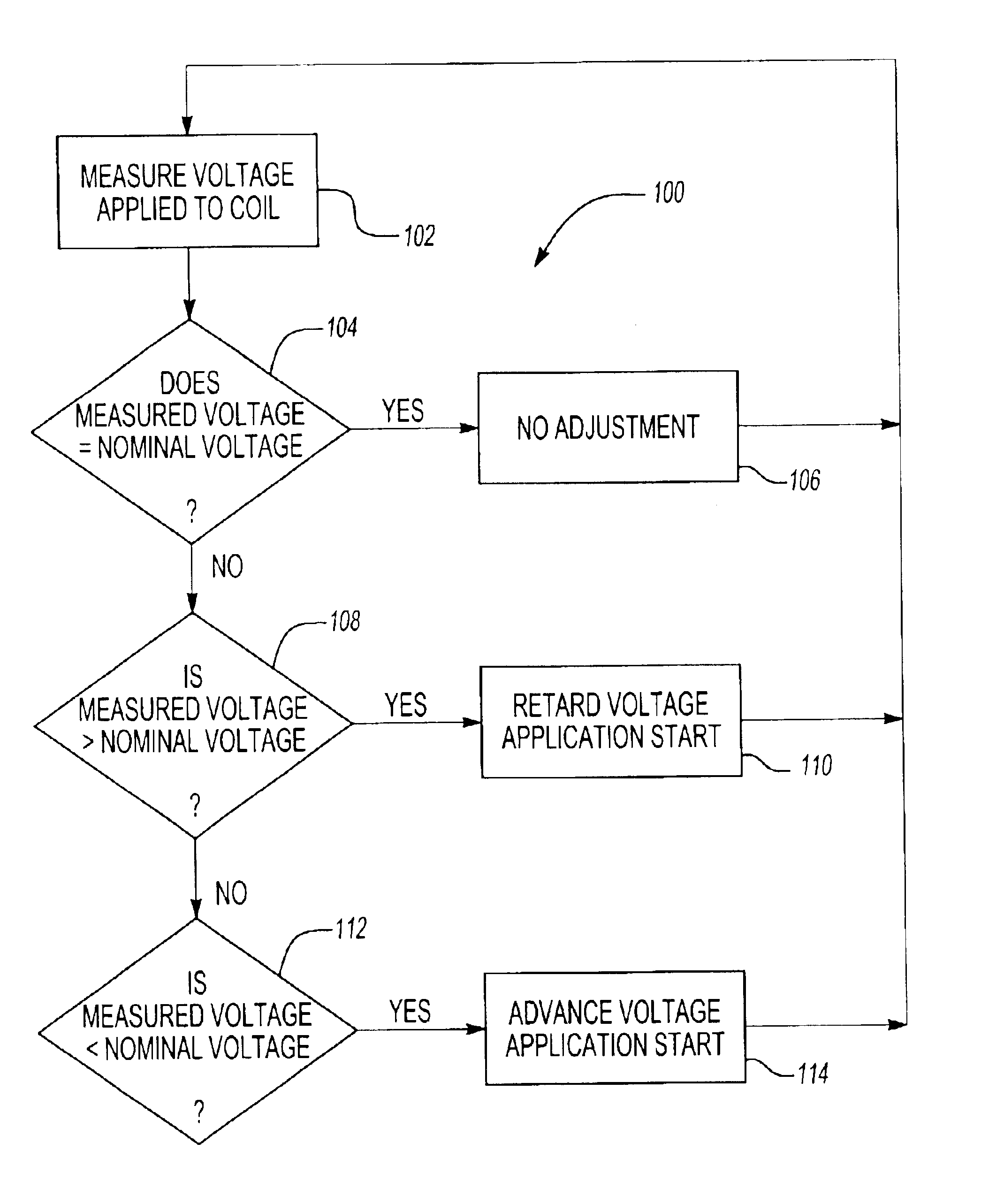
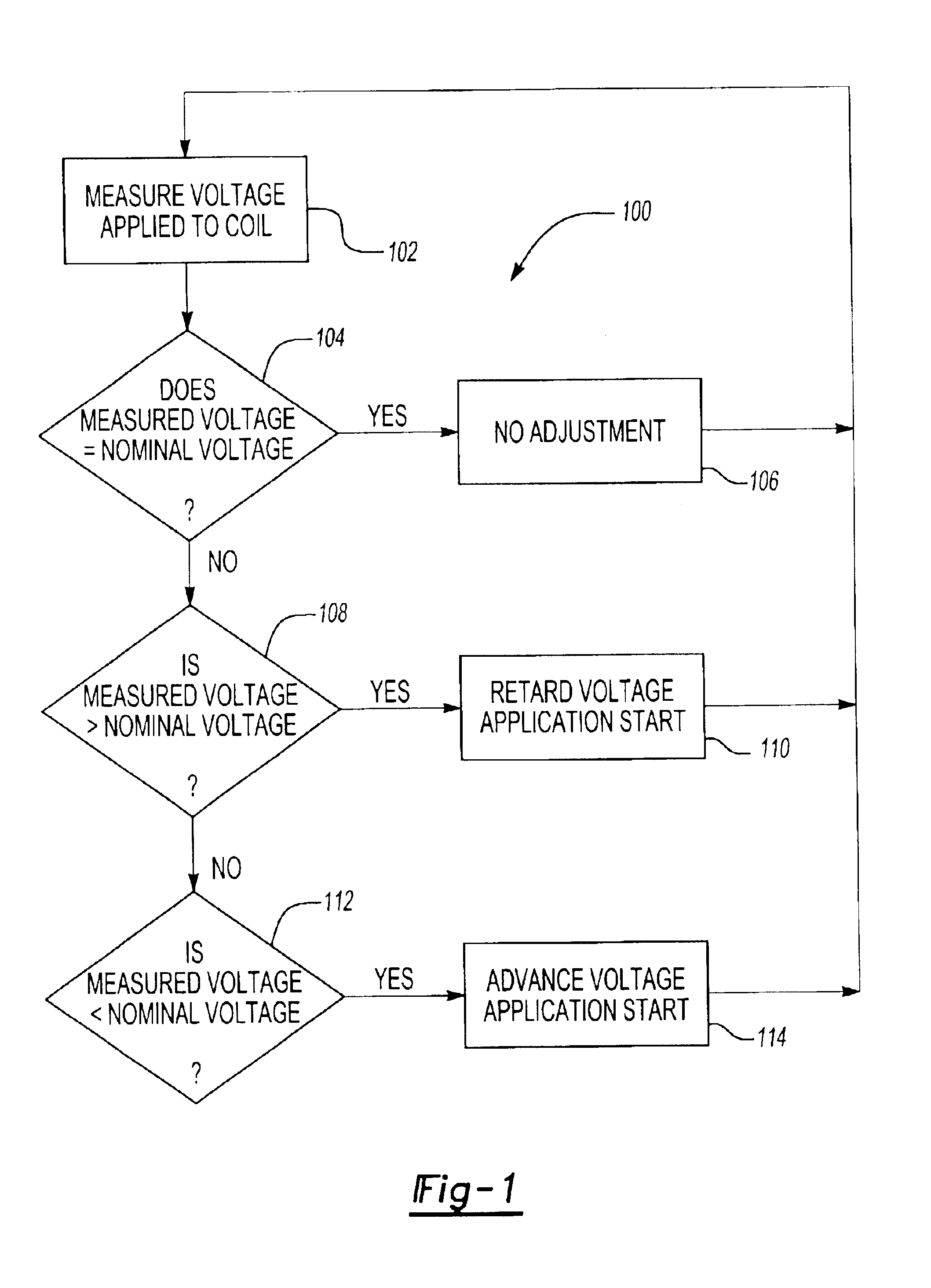
[0019]The inventive system and method generally involves adjusting the time at which voltage is applied to a coil in a fuel injection system to control the time at which fuel is actually injected into a cylinder of an engine. The description below provides two possible solutions for adjusting voltage application timing. The description below also provides one solution for adjusting load current.

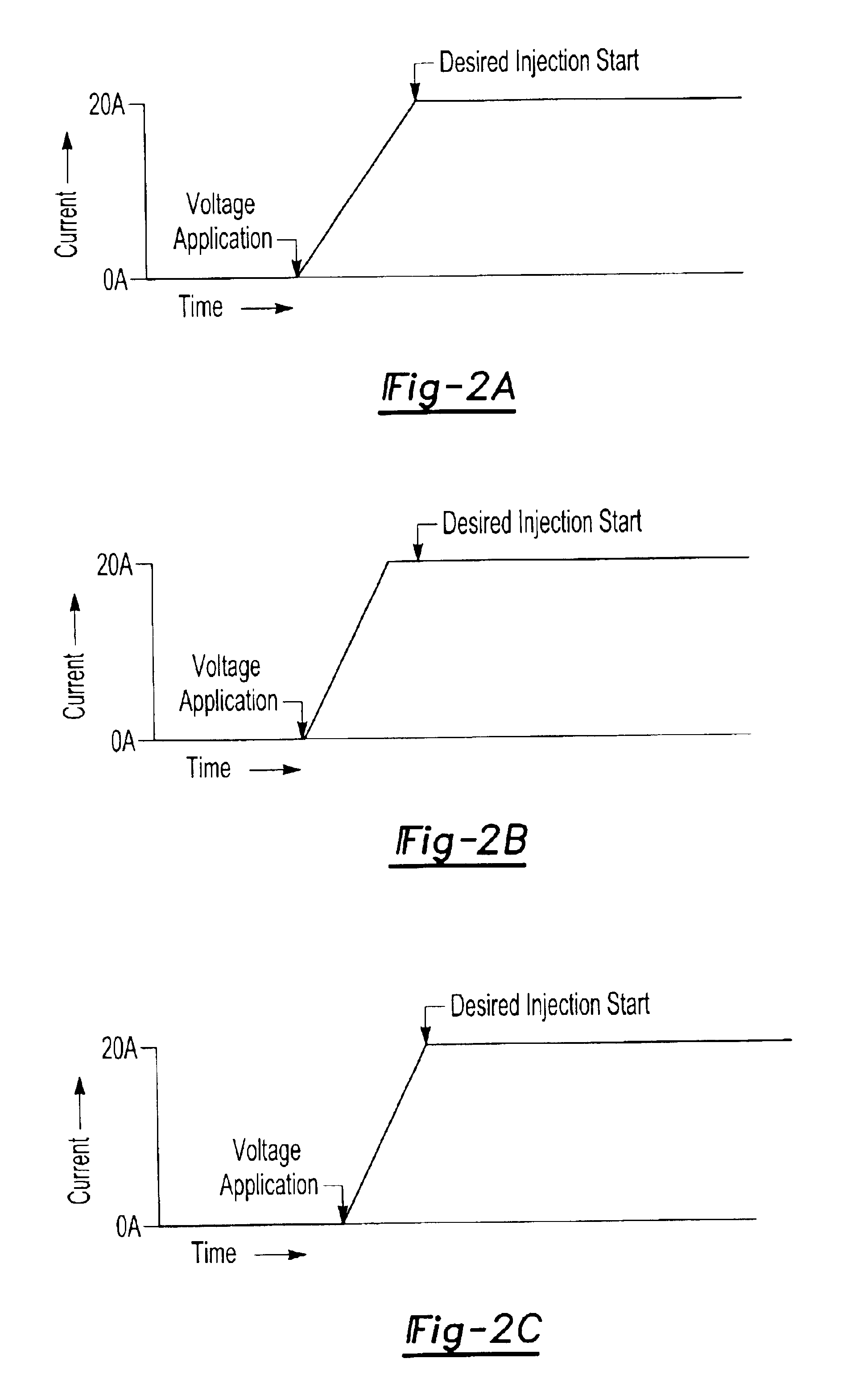
[0020]Injection timing relies on the relationship between a nominal voltage applied as a forward pulse to an injector coil and the time delay, or “ramp time” between the forward pulse and the time at which a load current in the injector coil rises to a desired level in response to the applied voltage. When the load current reaches the desired level, the injector starts injecting fuel into the engine. The load current is then maintained for a selected pulse width to continue fuel injection, then allowed to drop back down to zero. Because fuel should be injected at precise times during the engi...


PUM


Abstract

A fuel injector control system and method provides precise fuel injection timing while eliminating the need for a voltage regulator by estimating or predicting ramp times between voltage application and actual fuel injection. In one embodiment, an estimated ramp time injection is calculated from a measured voltage and is used to delay or advance application of the voltage on the coil so that the load current reaches a desired current level at a desired injection start time. In another embodiment, an actual ramp time for a given injection is measured and used to predict future ramp times. A current regulator prevents excessive emissions from being generated when controlling the load current.

Description

RELATED APPLICATIONS[0001]The present application claims priority to U.S. Provisional Patent Application Ser. Nos. 60 / 368,277, 60 / 380,108, and 60 / 380,705, filed Mar. 28, 2002, May 6, 2002, and May 15, 2002, respectively.TECHNICAL FIELD[0002]The present invention relates to fuel injection systems, and more particularly to a system that determines an optimum timing for fuel injection. The invention is also related to a method for controlling injector current.BACKGROUND OF THE INVENTION[0003]Fuel injection systems operate by energizing coils and using those coils to move an electromagnet that opens a valve, allowing pressurized fuel to enter the cylinders of an engine. The coils in fuel injectors tend to have a large amount of inductance, causing a delay between the time voltage is applied to the coil and the time that the coil has sufficient current flow (e.g., 20 A) to actually begin fuel injection. The actual amount of the delay depends both on the inductance of the coil and the amo...

Claims


Application Information

Patent Timeline
Patent Type & Authority Patents(United States)
IPC IPC(8): F02D41/20
CPCF02D41/20F02D2041/2003F02D2041/2017F02D2041/2031F02D2041/2034F02D2041/2051F02D2041/2075F02D2200/503
Inventor VIERLING, LOUTRACY, SHAWN LANCEHOLLOWELL, WILLIAM ELI
Owner VITESCO TECH USA LLC
Why Eureka
Try Eureka