Multi seam coal bed/methane dewatering and depressurizing production system

Inactive Publication Date: 2005-08-02
GARDES ROBERT
View PDF10 Cites 61 Cited by
  • Summary
  • Abstract
  • Description
  • Claims
  • Application Information

AI Technical Summary

Benefits of technology

[0018]It is a further object of the present invention to utilize underbalanced, multilateral drilling in coal bed methane recovery, having minimal environmental impact so that a single well can produce as much gas as eight traditional vertical wells on eighty acre spacing;
[0019]It i

Problems solved by technology

It has been recently found, that when such a hydrostatic head is placed on the formation, often times the heavy muds or fluids flow into the formation, and by doing so, create severe damage of the formation, which is a detriment to th

Method used


Image

  • Multi seam coal bed/methane dewatering and depressurizing production system
  • Multi seam coal bed/methane dewatering and depressurizing production system
  • Multi seam coal bed/methane dewatering and depressurizing production system

Examples


Embodiment Construction

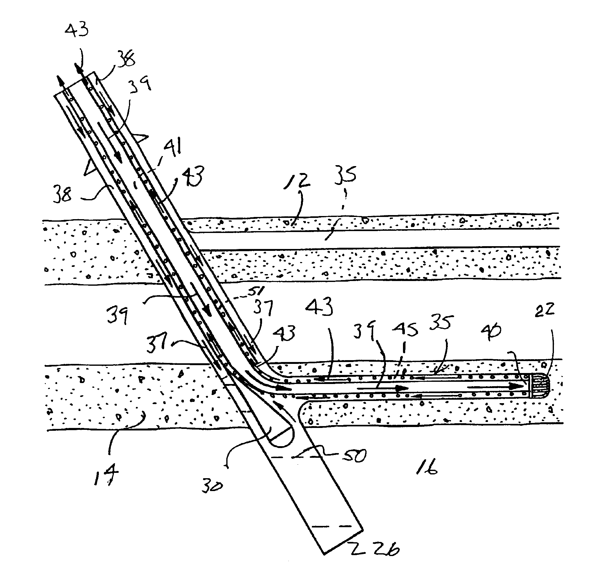
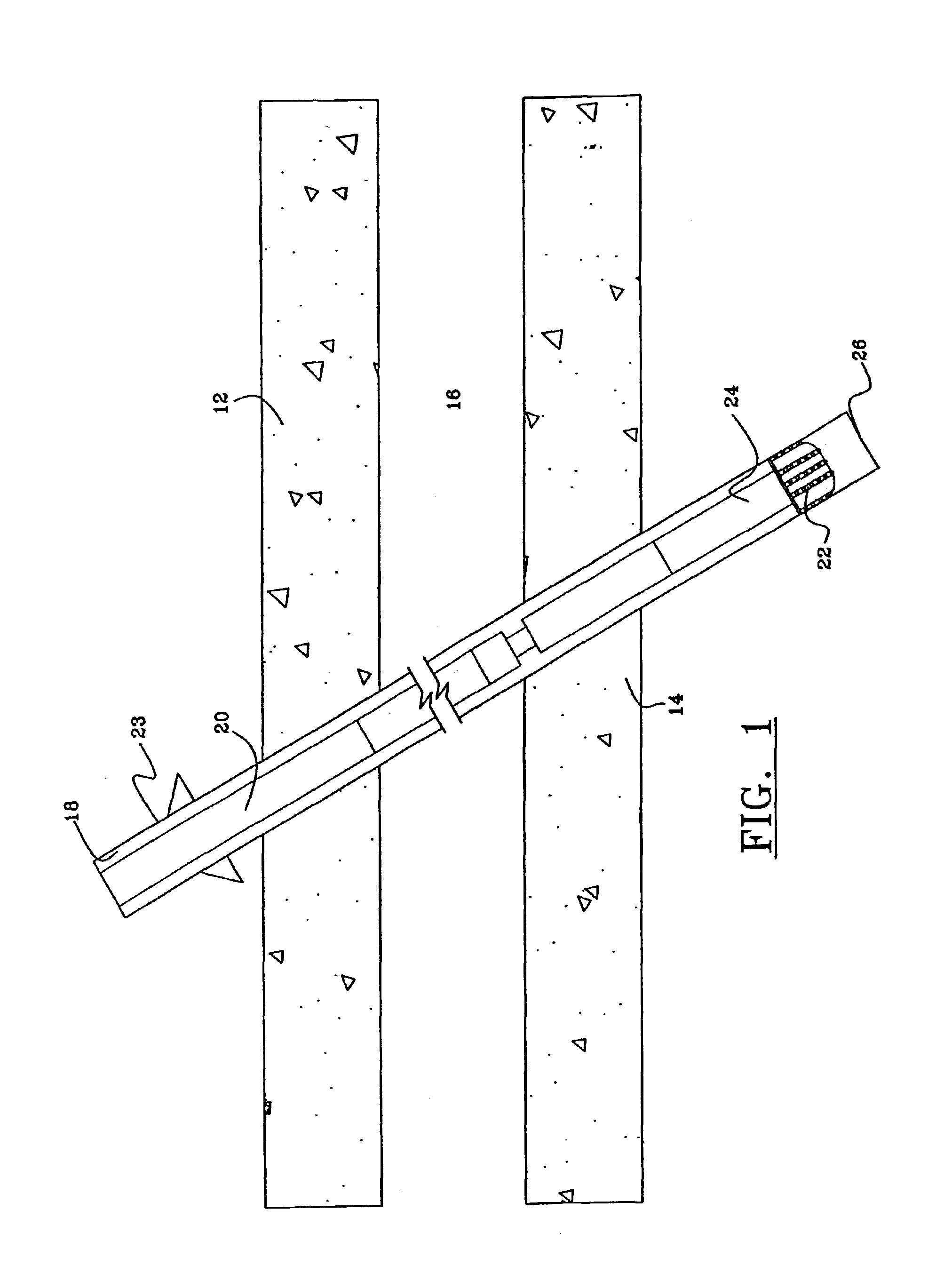
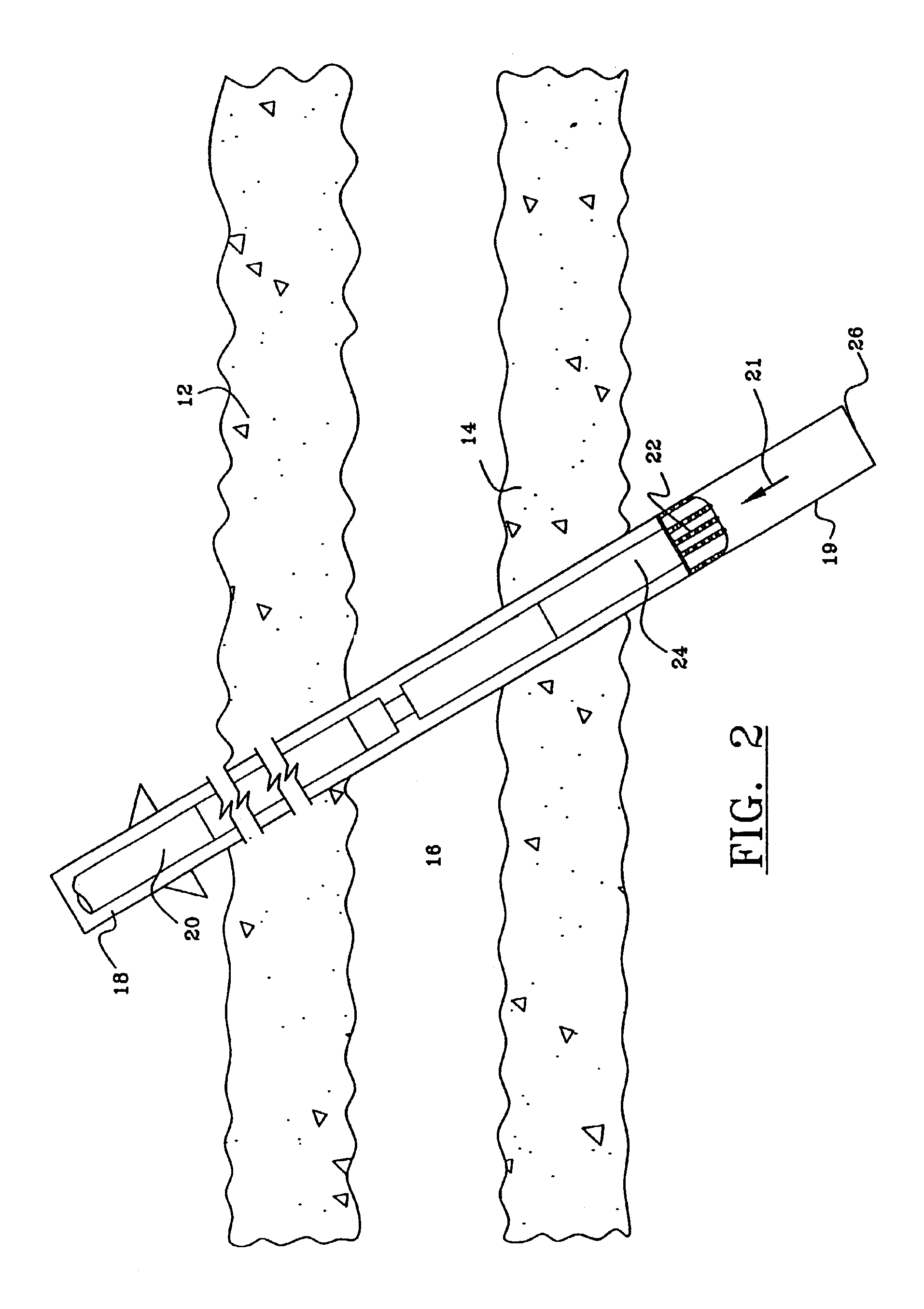
[0040]FIGS. 1-18 illustrate the preferred embodiment of the method of the present invention. As illustrated in FIG. 1, there is seen a first upper coal bed seam 12 and a second lower coal bed seam 14, the upper and lower coal bed seams 12, 14 set within a formation 16, above, between, and below the coal bed seams 12, 14, thousands of feet below the surface of the earth. Although coal seams 12, 14 are illustrated, it is foreseen for purposes of the invention, that there may be multiple coal seams involved in the process. However, for efficiency in explanation, reference will be made to two coal seams, 12, 14.

[0041]As illustrated further in FIG. 1, there is illustrated a directional borehole 18, which has been drilled through the first and second coal seams 12, 14. The directional borehole 18 has been drilled with traditional directional drilling techniques. There is further illustrated a drill string 20, having a drill bit 22 at its lower end, driven by a drill motor 24, to a particu...


PUM


Abstract

A process for underbalanced drilling into multiple coal and shale formations, and dewatering the drilled formations, which includes drilling a first borehole through several coal seams to a certain depth, defined as a cased borehole; lowering an upstock on the end of a carrier string to the depth of the upper coal seam; lowering a drill string in the carrier string, and angling off of the upstock, to drill a lateral or horizontal borehole within the coal seam; repeating the process for the second coal seam; setting a packer in place above the first coal seam in the annulus between the cased borehole and the carrier string; forming perforations in the wall of the carrier string below the packer; retrieving the upstock from the carrier string; lowering an electrical submersible pump to the bottom of the principal borehole, defined as a sump portion of the borehole; collecting methane gas from the two coal seams through the annulus between the second drill string and the carrier string to the surface; pumping water from the sump portion to the surface within the annulus of the second drill string, while gas within the annulus between the carrier string and the outer casing enters the plurality of perforations in the carrier string to be carried up to the surface.

Description

CROSS-REFERENCE TO RELATED APPLICATIONS[0001]This application claims priority of provisional patent application entitled “MULTI LENSE COAL BED / METHANE DEWATERING AND PRODUCTION SYSTEM,” Ser. No. 60 / 384,871, filed on May 31, 2002, and provisional patent application entitled “MULTI LENSE COAL BED / METHANE DEWATERING AND PRODUCTION SYSTEM,” Ser. No. 60 / 388,696, filed on Jun. 14, 2002, both by the same inventor, both of which are fully incorporated herein by reference thereto.[0002]This is a continuation-in-part application of co-pending U.S. patent application Ser. No. 10 / 262,557 filed Sep. 30, 2002, entitled “Method and System for Hydraulic Friction Controlled Drilling and Completing Geopressured Wells Utilizing Concentric Drill Strings”, which was a continuation of patent application U.S. Ser. No. 09 / 771,746, filed Jan. 29, 2001, by the same title, which issued as U.S. Pat. No. 6,457,540, on Oct. 1, 2002, both of which are incorporated herein by reference.STATEMENT REGARDING FEDERALLY...

Claims


Application Information

Patent Timeline
IPC IPC(8): E21B43/00E21B43/34E21B41/00E21B43/38E21B43/40E21B21/00
CPCE21B41/0035E21B43/006E21B43/385E21B43/40E21B2021/006E21B21/085
Inventor GARDES, ROBERT
Owner GARDES ROBERT
Why Eureka
Try Eureka