Friction brake

a technology of friction brakes and clamping devices, which is applied in the field of friction brakes, can solve the problems of affecting the operation of the brake, so as to achieve the effect of precisely controlling the brake actuation and improving the function

Inactive Publication Date: 2005-08-02
CONTINENTAL TEVES AG & CO OHG
View PDF14 Cites 5 Cited by
  • Summary
  • Abstract
  • Description
  • Claims
  • Application Information

AI Technical Summary

Benefits of technology

[0013]A preferred compact variant of the friction brake results from that the clamping device and the friction clutch are arranged in a brake housing of the friction brake. Thus the single components of the friction brake are not only protected with regard to environmental influences, but allow also a space-saving overall construction. Furthermore the arrangement of the friction clutch within the brake housing facilitates the sealing against the environment of the friction brake. First of all easy-to-design seals can be used here.
[0015]A further field of application for a friction brake according to the present invention is obtained by that the friction brake includes a friction element with several friction rings being arranged in axial distance to each other and upon which respective brake linings have a tribological effect. Thus also a disc brake with several friction rings can be provided with a generic clamping device as well as a friction clutch. In this case, a design with several clamping devices respectively friction clutches with at least one clamping device respectively friction clutch being arranged between two friction rings seems to be advantageous.

Problems solved by technology

Yet, the high-performance brake clamping devices and energy sources are not only expensive, but present also disadvantages with regard to their weight and their dimensions.
Above all, this has a negative effect on such friction brakes that are provided with brake clamping devices being operated electrically, electromechanically or by an electric motor.
The ball and ramp arrangement, however, presents the disadvantage of having a limited clamping path, which may be insufficient in case of very worn-out brake linings.
The disadvantage of such an arrangement certainly is that very large components with a relatively high moment of inertia have to be put into rotation within the friction brake.
Due to the direct frictional engagement with the brake disc, the friction clutch is also subject to the thermal influences of the brake disc that affect its function and may have a negative effect on the friction value within the friction clutch.
Furthermore friction clutch and toothed wheels for the clamping device are exposed without protection to environmental influences, as e.g. dirt and humidity.

Method used


Image

  • Friction brake
  • Friction brake
  • Friction brake

Examples


Embodiment Construction

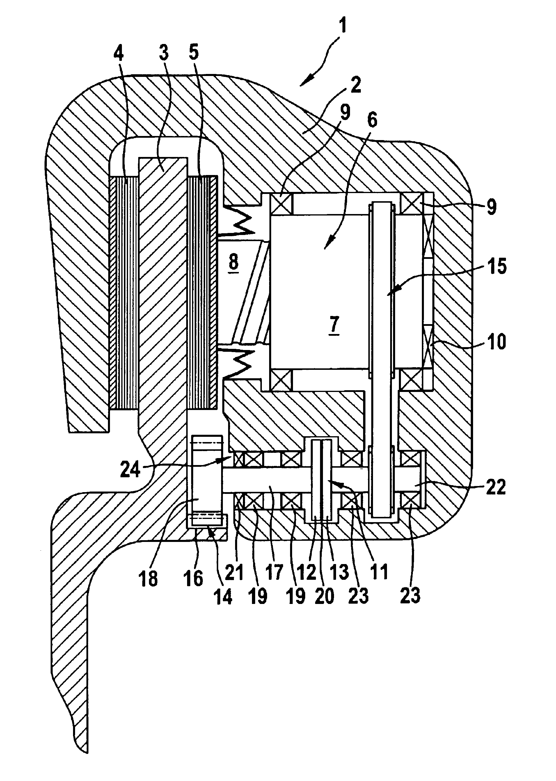
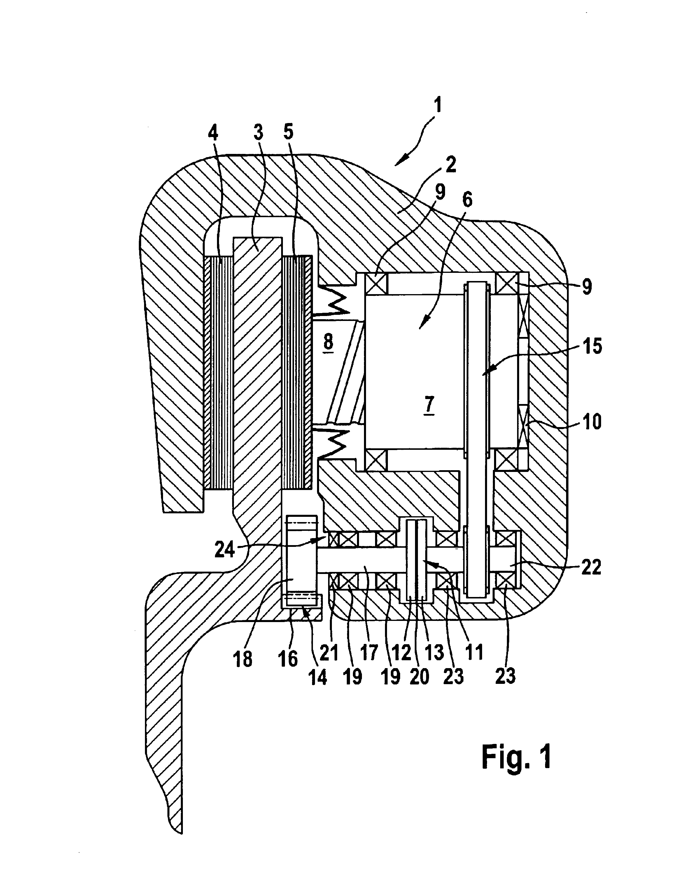
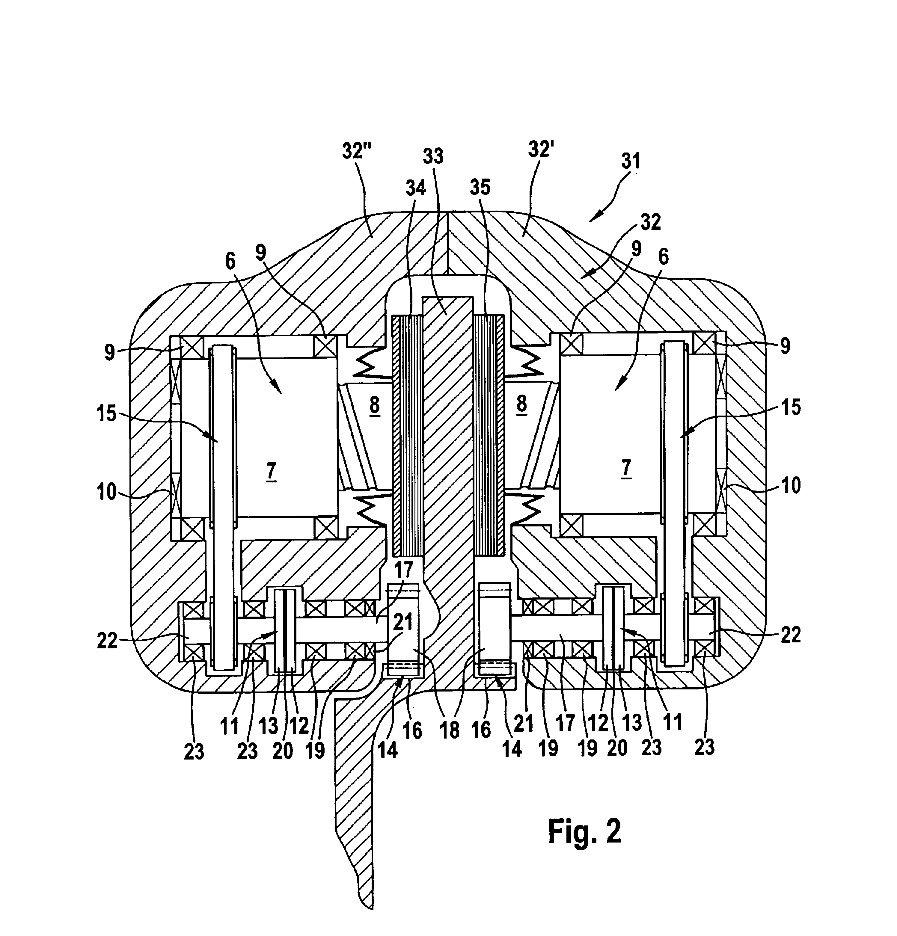
[0022]The Figures show several embodiments of a friction brake 1, 31, 41, 51 of a motor vehicle, designed as disc brake, which embraces with each brake housing 2, 32, 42, 52 one brake disc 3, 33, 43, 53 as well a brake linings 4,5 arranged on both sides of the brake disc 3, like a caliper. The disc brake 1 in FIG. 1 is designed as floating-caliper disc brake, the brake housing 2 of which being supported in a displaceable manner on a component mounted on the vehicle. The brake disc 3 is connected in an unrotatable manner with a vehicle wheel, which is not shown or coupled at least to the rotation of a vehicle wheel. Disc brake 1 is provided with one clamping device 6 acting at least upon one brake lining 5 in order to clamp the disc brake 1 during the actuation of the brake. The clamping device 6 on its part is coupled to the rotation of the brake disc 3 by means of a controllable friction clutch 11 inserted in between. For this reason, gear stages 14, 15 are provided between one inp...


PUM


Abstract

The present invention relates to a friction brake, in particular a disc brake, for a motor vehicle with a friction element, e.g. a brake disc, coupled to the rotation of a vehicle wheel, forming a friction pairing of the friction brake with at least one associated brake lining, and with at least one clamping device for pressing at least one brake lining to the friction element. At least one controllable friction clutch is provided for using the rotational energy of the friction element in order to obtain the clamping force of the friction brake, the friction clutch being coupled on its input end to the rotation of the friction element and on its output end to the clamping device. Functional advantages are achieved because a friction pairing of the friction clutch is provided independently of the friction pairing of the friction brake. This eliminates undesired mutual influences. Altogether, such a friction brake obviates the need for an additional energy source for generating a brake clamping force.

Description

BACKGROUND OF THE INVENTION[0001]The present invention relates to a friction brake, in particular a disc brake, for a motor vehicle with a friction element, e.g. a brake disc, coupled to the rotation of a vehicle wheel and brake linings assigned to it which can be pressed against the friction element by a disc brake clamping device.[0002]Due to high demands of said friction brakes with regard to the brake clamping force as well as the tension force dynamics, especially within modern controllable brake systems, usually high-performance brake clamping devices and related energy sources are necessary. Yet, the high-performance brake clamping devices and energy sources are not only expensive, but present also disadvantages with regard to their weight and their dimensions. Above all, this has a negative effect on such friction brakes that are provided with brake clamping devices being operated electrically, electromechanically or by an electric motor.[0003]In DE 42 07 640 C2 a motor vehi...

Claims


Application Information

Patent Timeline
IPC IPC(8): F16D65/14F16D69/00F16D65/18
CPCF16D65/18F16D2069/003F16D2121/14F16D2121/20F16D2125/40F16D2125/48F16D2127/12
Inventor HALASY-WIMMER, GEORGSCHMITT, STEFAN JOHANNESPOHLMANN, ANDREASGORLACH, JOHANNES
Owner CONTINENTAL TEVES AG & CO OHG
Why Eureka
Try Eureka