Foaming liquid dispenser

Active Publication Date: 2005-08-02
WESTROCK DISPENSING SYST
View PDF45 Cites 48 Cited by
  • Summary
  • Abstract
  • Description
  • Claims
  • Application Information

AI Technical Summary

Benefits of technology

[0012]In addition, three check valves are positioned along the length of the liquid discharge passage in the pump plunger. One check valve controls the flow of liquid into the liquid pump chamber and prevents the reverse flow. The second check valve controls the flow of liquid from the liquid pump chamber to the discharge passage and prevents the reverse flow. The third check valve controls the flow of air from the air pump chamber to the discharge passage and prevents the reverse flow.
[0013]The third check valve that controls the flow of air out of the pump chamber into the discharge passage and prevents the reverse flow of air from the discharge passage into the pump chamber is a resilient tube valve. The tube valve engages against the interior surface of the liquid discharge passage. Valve openings in the pump plunger communicate the exterior surface of the tube valve with the interior of the air pump chamber. The novel construction of the tube valve permits the flow of air under pressure from the air pump chamber to the discharge passage and prevents the reverse flow of air from the discharge passage to the air pump chamber. The tube valve is the only valve that controls the flow of air into and out of the air pump chamber, eliminating the additional valve present in prior art foaming dispensers that mix liquid and air under pressure.
[0014]The air pump chamber of the invention has a cylindrical interior surface with a first, upper section and a second, lower section. The interior diameter of the air pump chamber first section is slightly larger than that of the air pump chamber second section. In addition, the air pump piston exterior surface has a first section and a second section. The exterior diameter of the second section of the exterior surface is larger than the exterior diameter of the first section of the exterior surface. The exterior diameter of the second section of the air pump piston exterior surface is also larger than the interior diameter of the second section of the air pump chamber interior surface, but is smaller than the interior d

Problems solved by technology

However, the foaming trigger sprayers cannot produce a more dense foam such as that of shaving cream.
These additi

Method used


Image

  • Foaming liquid dispenser
  • Foaming liquid dispenser
  • Foaming liquid dispenser

Examples


Embodiment Construction

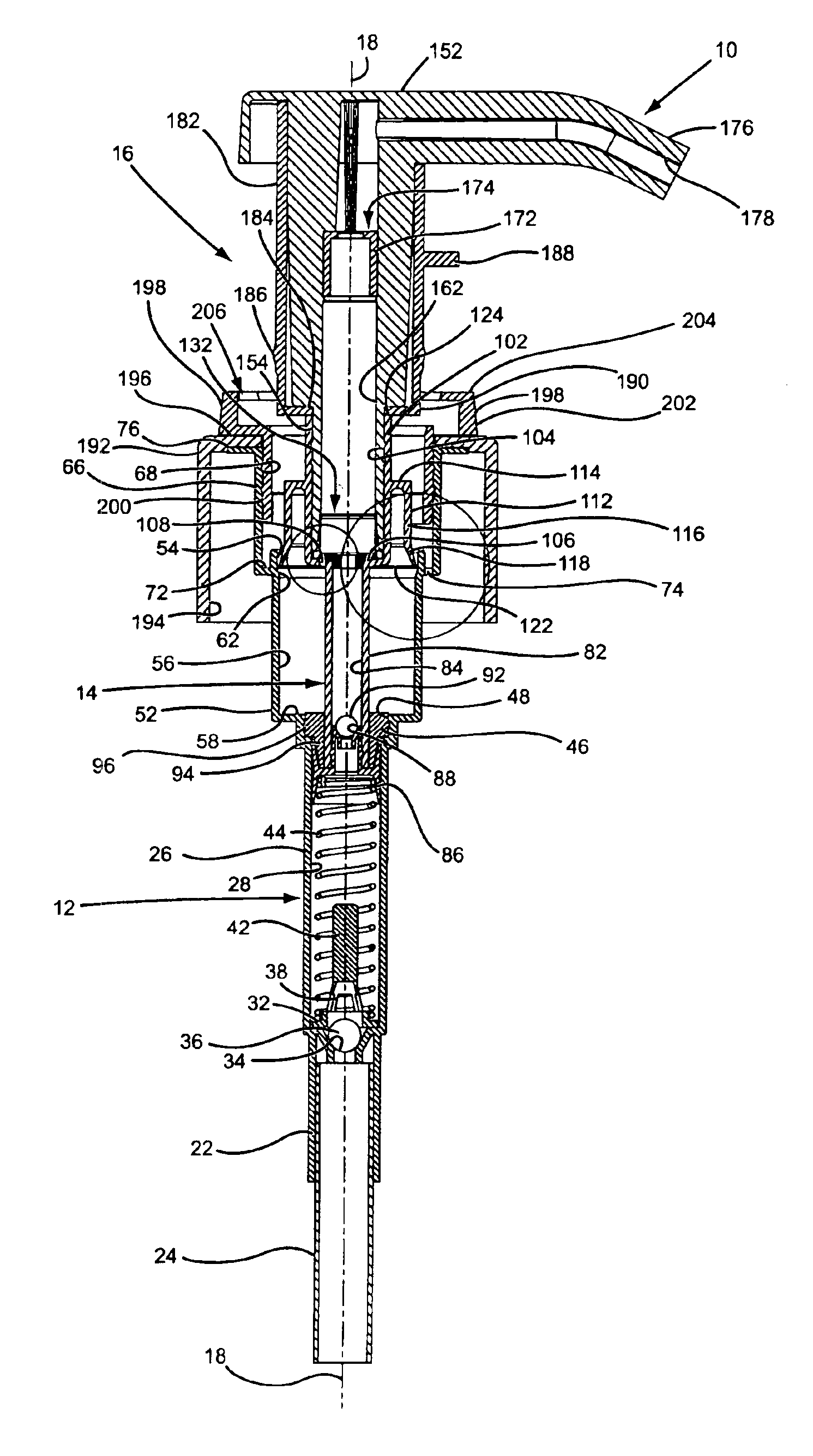
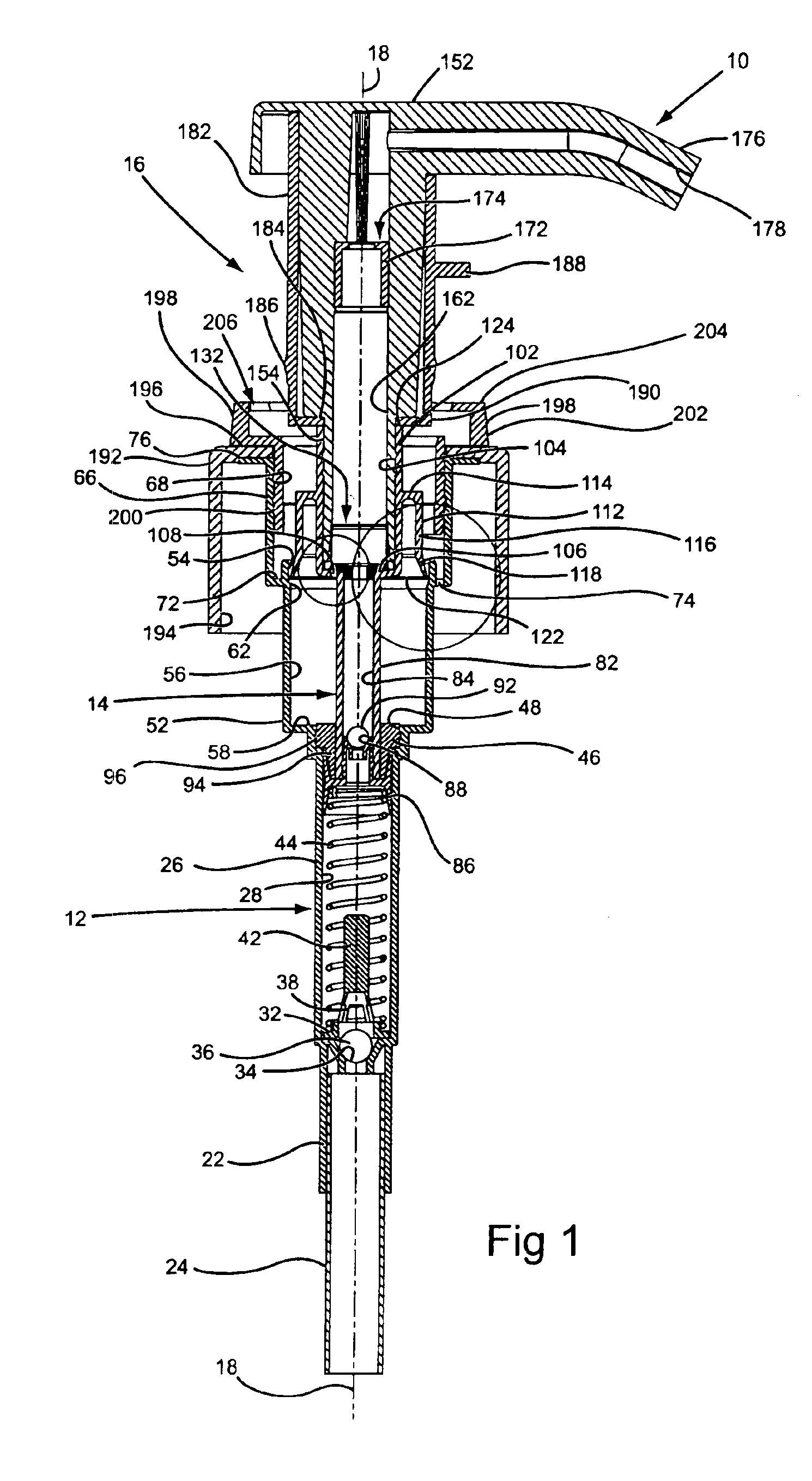
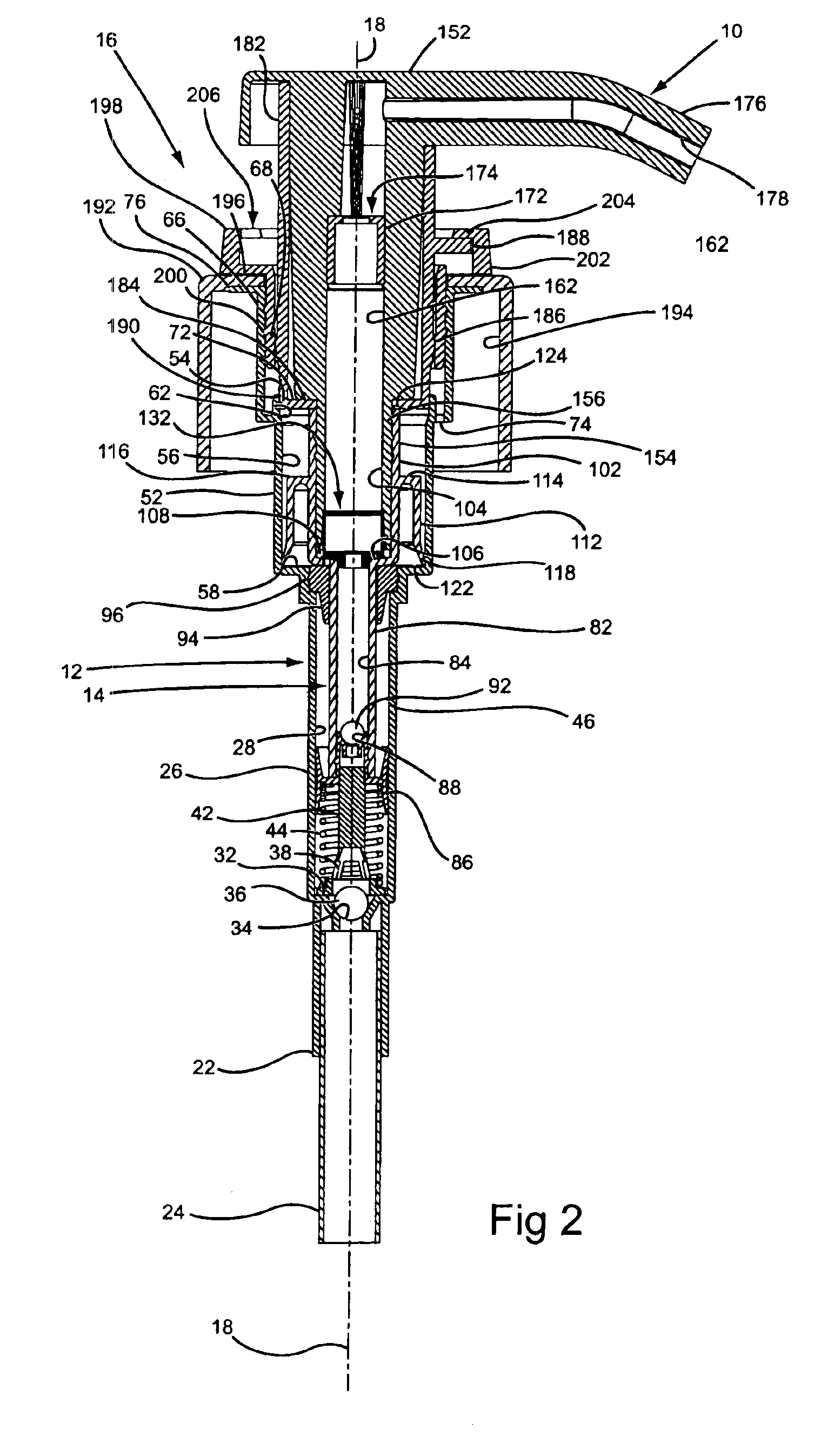
[0029]The liquid foaming dispenser 10 of the present invention is similar to the types of dispensers known in the art as lotion dispensers. These types of dispensers are typically operated by orienting the dispenser vertically upright. In the description of the liquid foaming dispenser of the invention to follow, the terms “top” and “bottom”, “upper” and “lower” or similar related terms will be used to describe the component parts of the dispenser. These terms are only used because the dispenser is typically oriented vertically upright when using the dispenser. The terms should not be interpreted as limiting.

[0030]The liquid foaming dispenser 10 shown in FIGS. 1 and 2 is basically comprised of a pump housing 12, a pump plunger 14 and a container cap and lock assembly 16. The materials employed in constructing the component parts of the dispenser are the same as those typically used in the industry, usually plastics except for a metal coil spring employed in the pump. Apart from the ...


PUM


Abstract

A manually operated liquid foaming dispenser is attached to the top of a container of liquid and is manually vertically reciprocated to dispense the liquid from the container as a foam. The dispenser includes a liquid pump chamber and an air pump chamber that respectively pump liquid and air to a discharge passage of the pump where the liquid and air are mixed, generating the foam dispensed from the dispenser. The liquid dispenser is constructed with three biased closed valves that prevent leakage from a liquid container attached to the dispenser should the dispenser and container be positioned on their sides or be inverted.

Description

CROSS-REFERENCE TO RELATED APPLICATIONS[0001]This application is a continuation-in-part of application Ser. No. 10 / 288,831, which was filed on Nov. 6, 2002 now U.S. Pat. No. 6,644,516.BACKGROUND OF THE INVENTION[0002]1. Field of the Invention[0003]The present invention pertains to a manually operated liquid foaming dispenser. Specifically, the invention pertains to a manually operated pump that is attached to the top of a bottle of liquid and is manually vertically reciprocated to dispense the liquid from the container as a foam. The pump includes a liquid pump chamber and an air pump chamber that respectively pump liquid and air under pressure to a discharge passage of the pump where the liquid and air are mixed, generating the foam dispensed from the pump.[0004]2. Field of the Invention[0005]Manually operated liquid dispensers that dispense liquid as a foam are known in the prior art. The most well known of these types of dispensers are manually operated trigger sprayers that pump...

Claims


Application Information

Patent Timeline
IPC IPC(8): B05B7/00B05B11/00A47KB67D7/60B65D47/34B67D7/76G01F11/02
CPCB05B7/0031B05B11/306B05B11/3087G01F11/028B05B11/106B05B11/1087
Inventor FOSTER, DONALD D.NELSON, PHILIP L.
Owner WESTROCK DISPENSING SYST
Why Eureka
Try Eureka