Image forming device

a technology of forming device and forming plate, which is applied in the direction of thin material processing, electrographic process apparatus, instruments, etc., can solve the problems of increasing the size and cost of the printer, affecting the printing speed, so as to increase the time interval, increase the transport distance of sheets and the transport speed, and increase the printing speed

Inactive Publication Date: 2005-08-02
RICOH PRINTING SYST
View PDF9 Cites 5 Cited by
  • Summary
  • Abstract
  • Description
  • Claims
  • Application Information

AI Technical Summary

Benefits of technology

[0012]In order to overcome the above-described problems, it is conceivable to increase both the transport distance of sheets and the transport speed when increasing the printing speed. This would increase the time interval between successive sheets. However, such a conceivable configuration would require a larger motor for driving the transport mechanism at the faster transport speed. The larger motor would increase the size and cost of the printer.
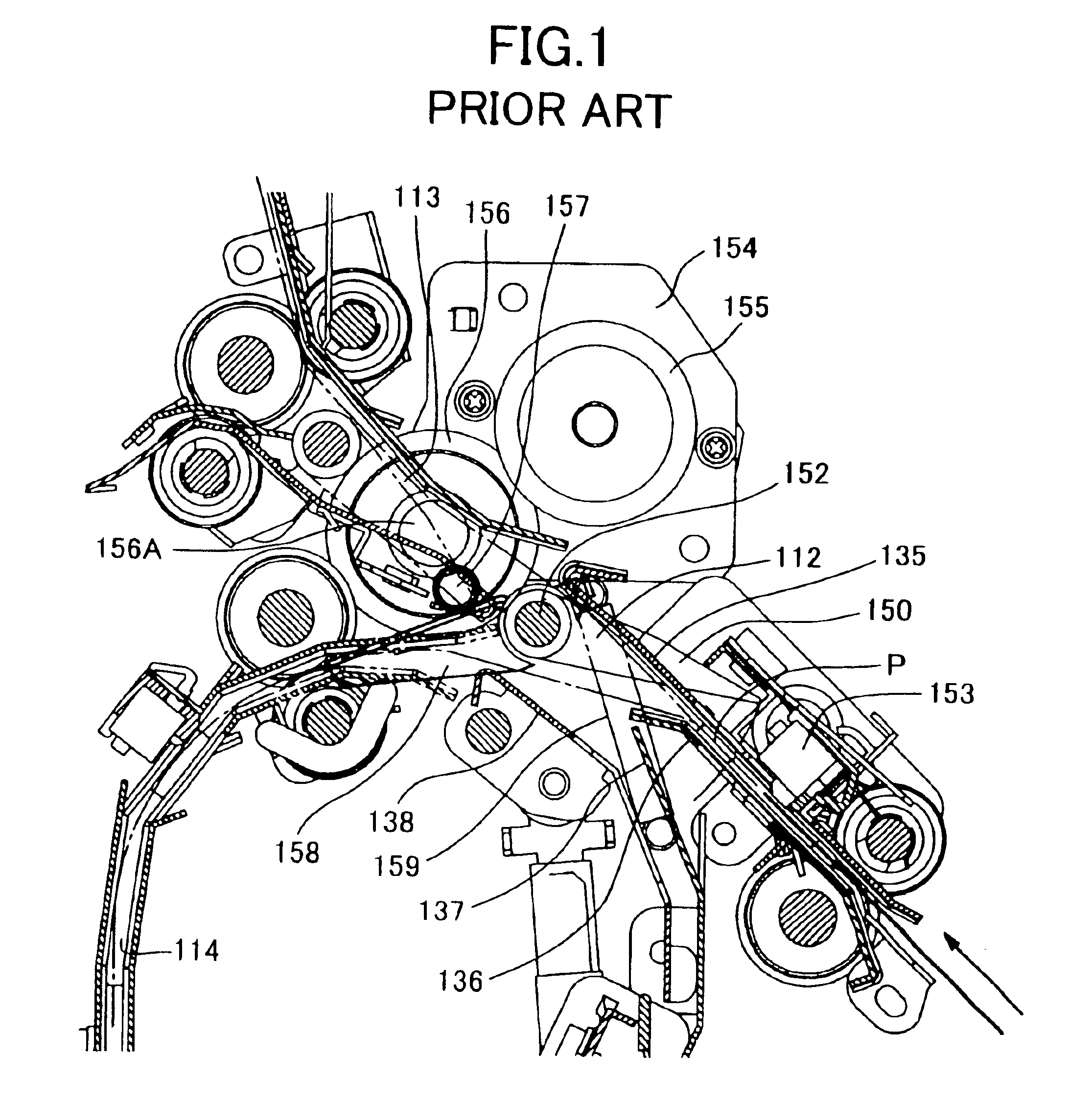
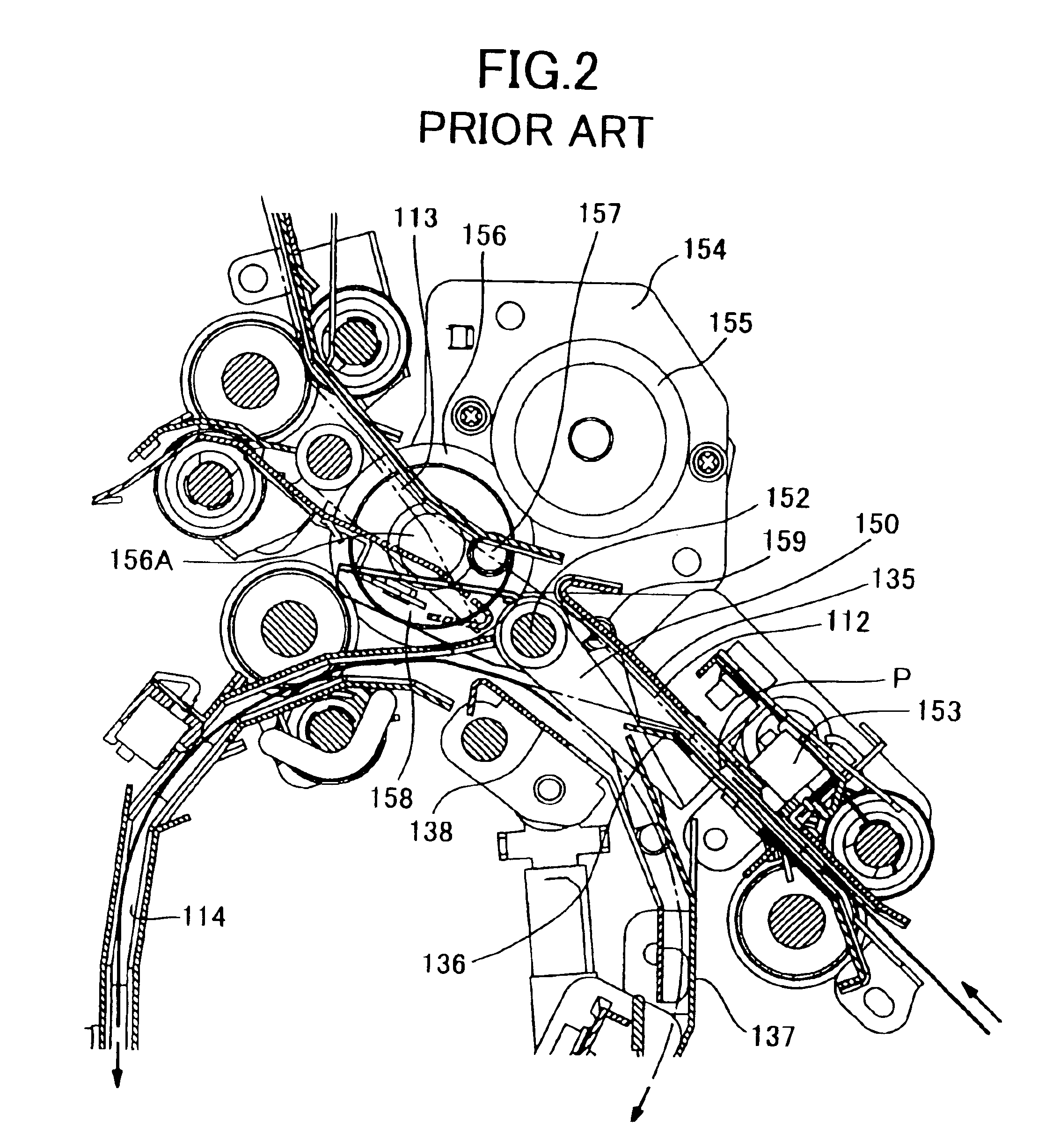
[0013]Alternatively, it is conceivable to increase the rotational speed of the stepping motor 154 in association with increase in printing speed so that the path gate can be pivoted more rapidly. However, such a faster stepping motor 154 would increase the cost of the printer.
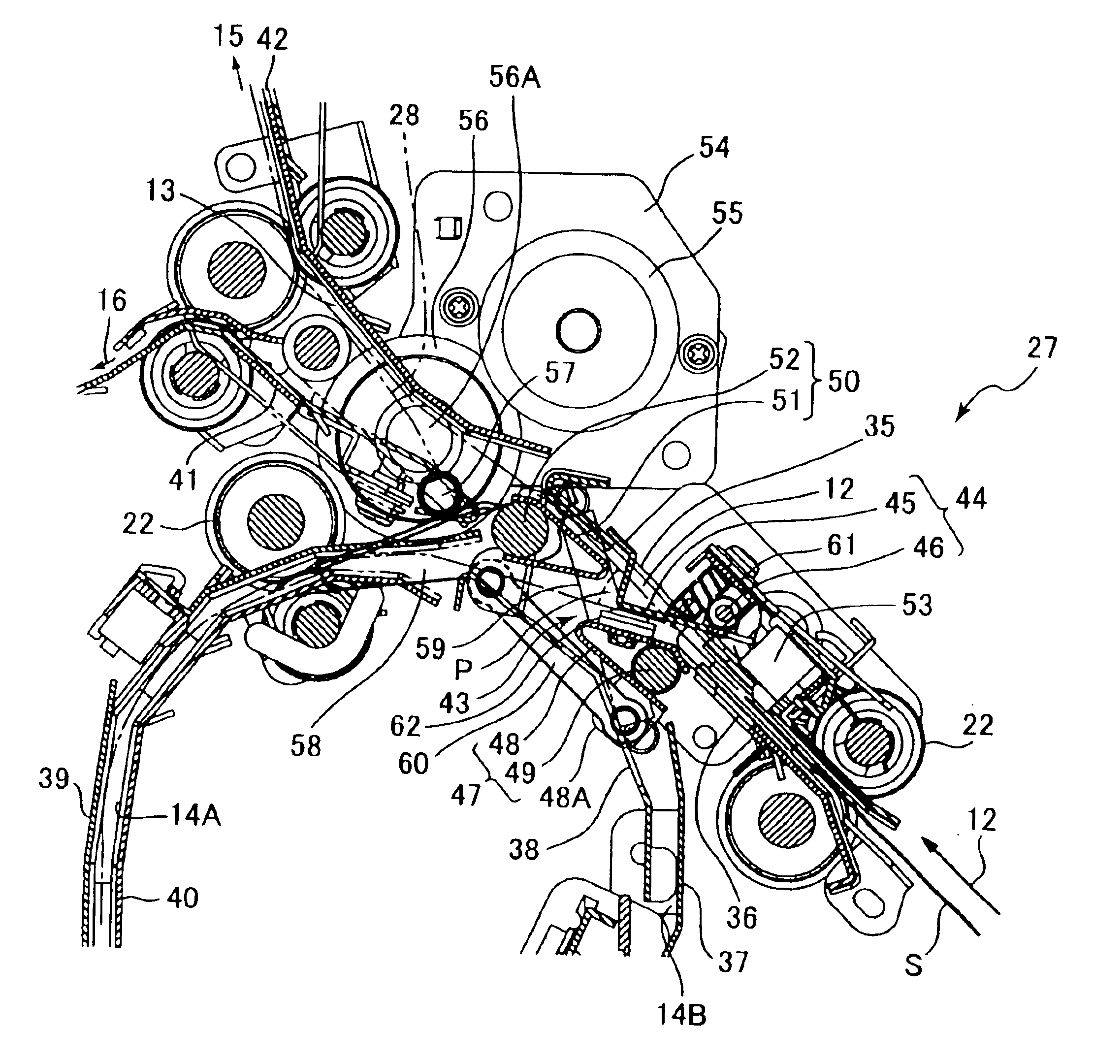
[0014]It is an objective of the present invention to overcome the above-described problems and to provide mechanism for switching sheet transport path in an image forming device using a gate member wherein the gate member has sufficient time to move even when sheet transport distance and transport speed are minimal.

Problems solved by technology

This pinching action can damage the sheet.
This can result in a paper jam.
The larger motor would increase the size and cost of the printer.

Method used


Image

  • Image forming device
  • Image forming device
  • Image forming device

Examples


Embodiment Construction

[0022]Next, a printer according to an embodiment of the present invention will be described based on FIGS. 3 to 5. As shown in FIG. 3, the printer includes an image forming section 1 and a sheet handling section 29. The image forming section 1 is a laser printer including a photosensitive drum 6 to form toner images on sheets using well-known electrophotographic processes. The sheet handling section 29 is a stacker that stacks sheets discharged from the image forming section 1 onto trays.

[0023]The image forming section 1 includes a main casing 2. A plurality of sheet holding units 3, 4, 5 are aligned one on top of each other in the lower section of the main casing 2. The sheet holding units 3, 4, 5 hold sheets on which the image forming section 1 forms images. A photosensitive drum 6 is provided above the sheet holding units 3, 4, 5. The photosensitive drum 6 is supported rotatable in the direction indicated by arrow A in FIG. 3 based on signals from a controller (not shown). A coro...


PUM


Abstract

An image forming device includes an upstream-side sheet transport pathway, a plurality of downstream-side sheet transport pathways, and a pathway switching mechanism. The plurality of downstream-side sheet transport pathways diverge from the upstream-side sheet transport pathway at a divergence point. At the divergence point, the pathway switching mechanism selectively guides sheets that were transported following the upstream-side sheet transport pathway to one of the plurality of downstream-side sheet transport pathways. The pathway switching mechanism includes a pair of upstream-side gate members and a gate member pivoting unit. The pair of upstream-side gate members include a pair of pivot shafts and a pair of gates. The pair of pivot shafts are disposed with the sheet transport pathway interposed therebetween. Each of the pair of gates is pivotable around a corresponding one the pair of pivot shafts and extends substantially toward the downstream-side sheet transport pathways. The gate member pivoting unit pivots the pair of gates substantially simultaneously and substantially in the same direction.

Description

BACKGROUND OF THE INVENTION[0001]1. Field of the Invention[0002]The present invention relates to an image forming device such as a printer or a copy machine, and more particularly to an image forming device that transports cuts sheets one at a time and that includes a transport pathway switching mechanism that guides the cut sheets selectively toward a sheet-discharge pathway and toward a sheet turn-over / resupply transport pathway.[0003]2. Description of Related Art[0004]There has been known a conventional printer capable of printing on both sides of the same sheet. The printer includes a transport pathway switching unit for switching transport pathway of sheets. The pathway switching unit is located downstream from an image fixing unit and other image forming components for forming an image on one side of a sheet. The pathway switching unit selectively guides sheets from the image fixing unit toward either a discharge pathway or a return pathway. The discharge pathway leads to a st...

Claims


Application Information

Patent Timeline
Patent Type & Authority Patents(United States)
IPC IPC(8): B65H29/60G03G15/00B65H5/38
CPCB65H29/60
Inventor HASHIMOTO, YASUSHI
Owner RICOH PRINTING SYST
Why Eureka
Try Eureka