Multiple material bumper beam

a bumper beam and multi-material technology, applied in the direction of bumpers, vehicular safety arrangments, transportation and packaging, etc., can solve the problems of reducing fuel efficiency, adding significant weight to the vehicle, and increasing the time and cost of the manufacturing process, so as to achieve less weight and high quality standards

Inactive Publication Date: 2005-08-02
MAGNA INTERNATIONAL INC +1
View PDF35 Cites 42 Cited by
  • Summary
  • Abstract
  • Description
  • Claims
  • Application Information

AI Technical Summary

Benefits of technology

[0006]The inventors of the present invention have recognized these and other problems associated with the traditional bumper beams described abov...

Problems solved by technology

Often, the strong metallic beam is heavy and adds significant weight to the vehicle thereby reducing fuel efficiency.
Complex bumper ...

Method used


Image

  • Multiple material bumper beam
  • Multiple material bumper beam
  • Multiple material bumper beam

Examples


first embodiment

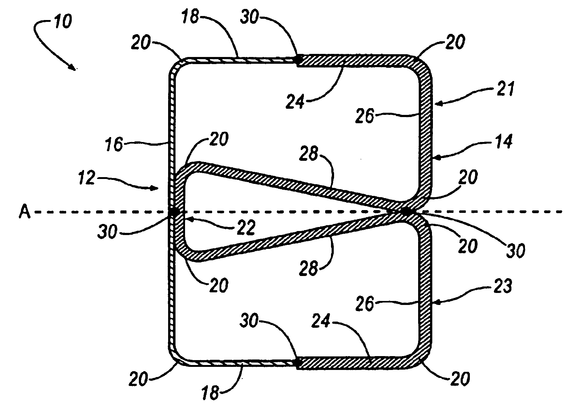
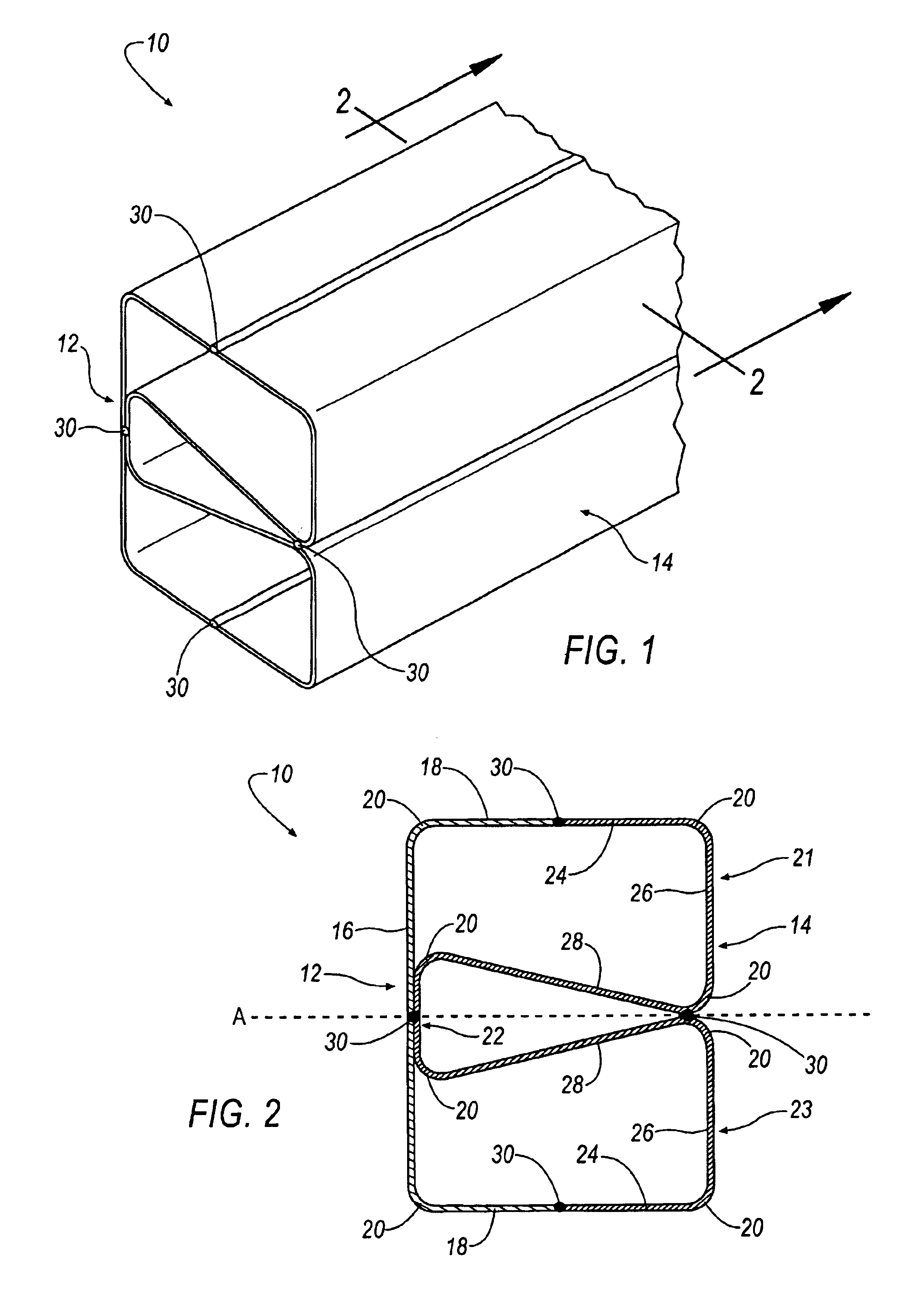
[0018]Referring to FIG. 2, a cross-sectional view of the bumper beam 10 is shown. As seen in FIG. 2, the first portion 12 is generally C-shaped in cross-section and includes a back 16 and two legs 18. The legs 18 extend generally orthogonally from the back 16 at one or more bending portions 20.

second embodiment

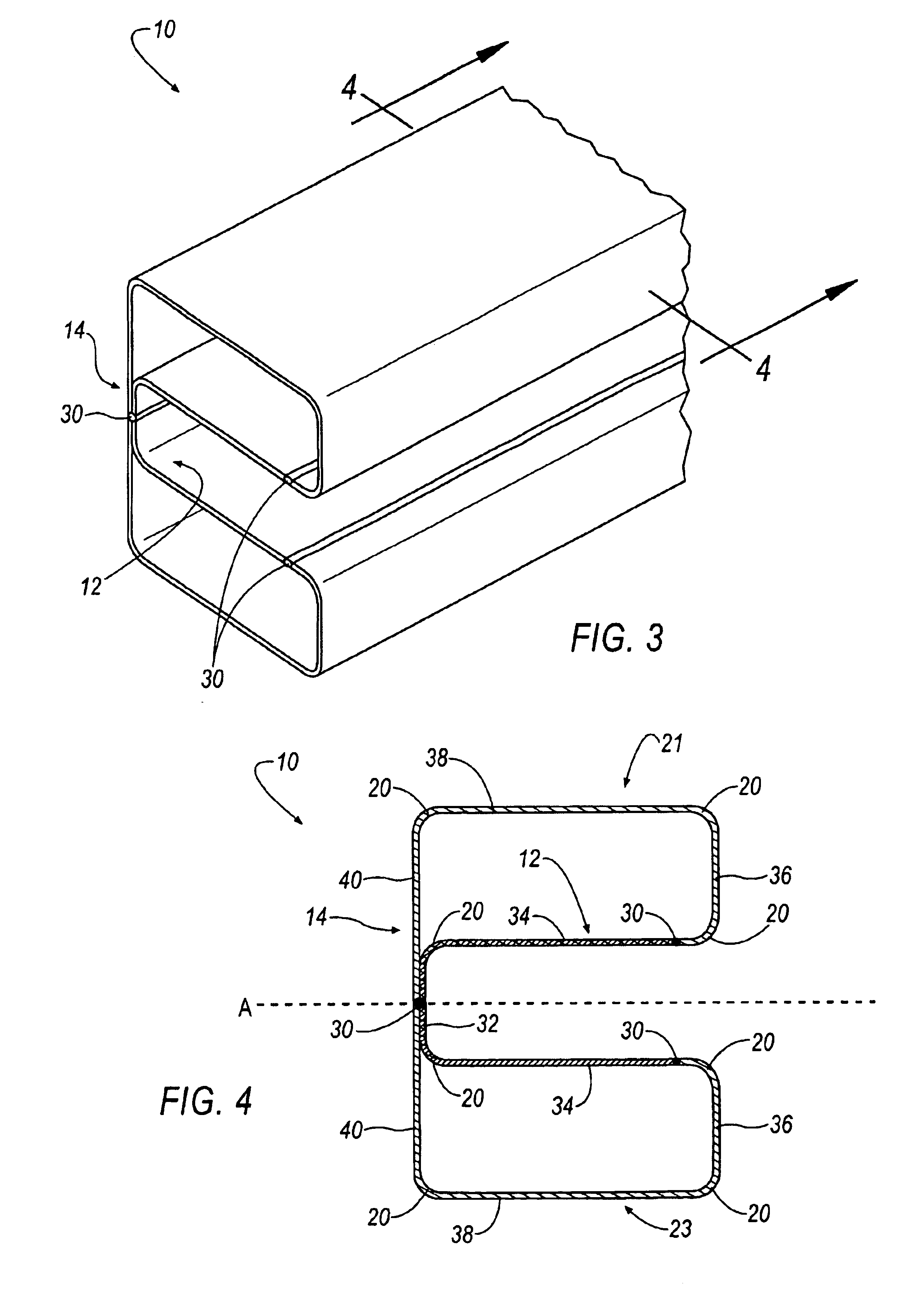
[0019]Referring to FIG. 4, a cross-sectional view of the bumper beam 10 is shown. As seen in FIG. 4, the first portion 12 is generally C-shaped in cross-section and includes a back 32 and two legs 34. The legs 34 extend generally orthongonally from the back 32 at one or more of the bending portions 20.

[0020]In the illustrated embodiments of the invention, the second portion 14 comprises a dual-phase, multiphase, complex-phase or transformation induced plastic (TRIP) steel. One such material determined suitable for the second portion 14 of the bumper beam 10 is currently marketed under the trade name DI-Form 140T. DI-Form 140T is commercially available from Ispat Inland Inc. of East Chicago, Ind. (www.ispat.com). DI-Form 140T has an ultimate tensile strength of approximately 965 MPa. Although the second material of the second portion 14 is generally of a lower strength than the first material of the first portion 12, the second material of the second portion 14 weighs less than or eq...


PUM


Abstract

A bumper beam includes a first portion of a first material and a second portion of a second material. The first material has different material properties than the second material. For example, the first material may have a generally higher tensile or yield strength than the second material. In one embodiment, the first material comprises martensitic steel, while the second material comprises a dual-phase, multiphase, complex-phase or TRIP steel. In addition, the first material may have a different thickness than the second material. The bumper beam provides an improved strength to weight ratio than conventional bumper beams. This abstract is provided to comply with the rules requiring an abstract that allows a searcher or other reader to quickly ascertain the subject matter of the disclosure. It is submitted with the understanding that it will not be used to interpret or limit the scope of the claims. 37 CFR 1.72(b).

Description

BACKGROUND OF THE INVENTION[0001]1. Field of the Invention[0002]The present invention relates to a bumper assembly for a motor vehicle, and more particularly to a bumper beam having multiple material properties.[0003]2. Description of the Related Art[0004]Automotive designers are continually trying to balance the need for lightweight, fuel efficient automobiles with safety standards and regulations imposed by the government and insurance companies. One such automotive component subject to heavy regulation is bumper assemblies with regard to crash safety standards. The bumper assembly is traditionally comprised of a bumper beam made of a metallic material with the requisite strength to conform to governmental standards for low and high speed crashes. Often, the strong metallic beam is heavy and adds significant weight to the vehicle thereby reducing fuel efficiency. There is a need in the automotive industry to develop a bumper assembly having a bumper beam with an increased strength...

Claims


Application Information

Patent Timeline
IPC IPC(8): B60R19/18
CPCB60R19/18B60R2019/1826E04C2003/0456
Inventor CUMMING, DAVID M.GABBIANELLI, GIANFRANCOMELLIS, JEFFERY J.UCHIYAMA, HIROSHI
Owner MAGNA INTERNATIONAL INC
Why Eureka
Try Eureka