Light emitting diode assembly for an illuminated sign

a technology of light emitting diodes and assembly parts, which is applied in the direction of electrical apparatus casings/cabinets/drawers, hermetically sealed casings, instruments, etc., can solve the problems of light emitting diode modules exposed to the outside from a case, deteriorating integration of the components thereof, and frequent shorting of connecting wires

Inactive Publication Date: 2005-08-02
ATTO DISPLAY
View PDF16 Cites 36 Cited by
  • Summary
  • Abstract
  • Description
  • Claims
  • Application Information

AI Technical Summary

Benefits of technology

[0017]As described above, in the light emitting diode assembly for an illuminated sign according to the preferred embodiment of the present invention, the light emitting diode assembly includes a case being open upwards. The printed circuit board is installed in the case and is mounted on u

Problems solved by technology

Accordingly, the integrity of the components thereof deteriorates because water penetrates into the inside of thereof.
Also, Light Emitting D

Method used


Image

  • Light emitting diode assembly for an illuminated sign
  • Light emitting diode assembly for an illuminated sign
  • Light emitting diode assembly for an illuminated sign

Examples


Embodiment Construction

[0023]Hereinafter, the light emitting diode assembly for an illuminated sign according to a preferred embodiment of the present invention will be explained in more detail with reference to the accompanying drawings.

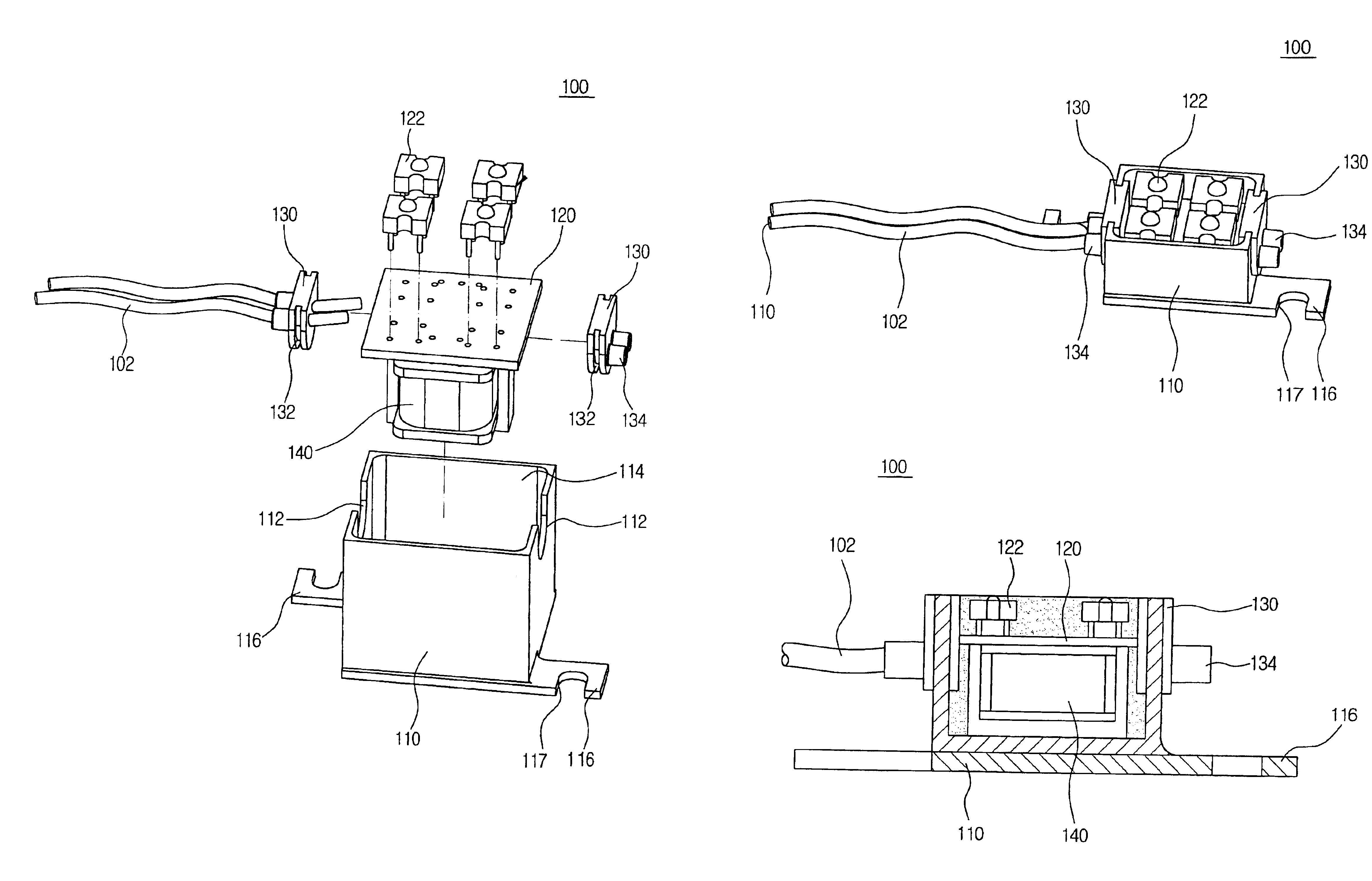
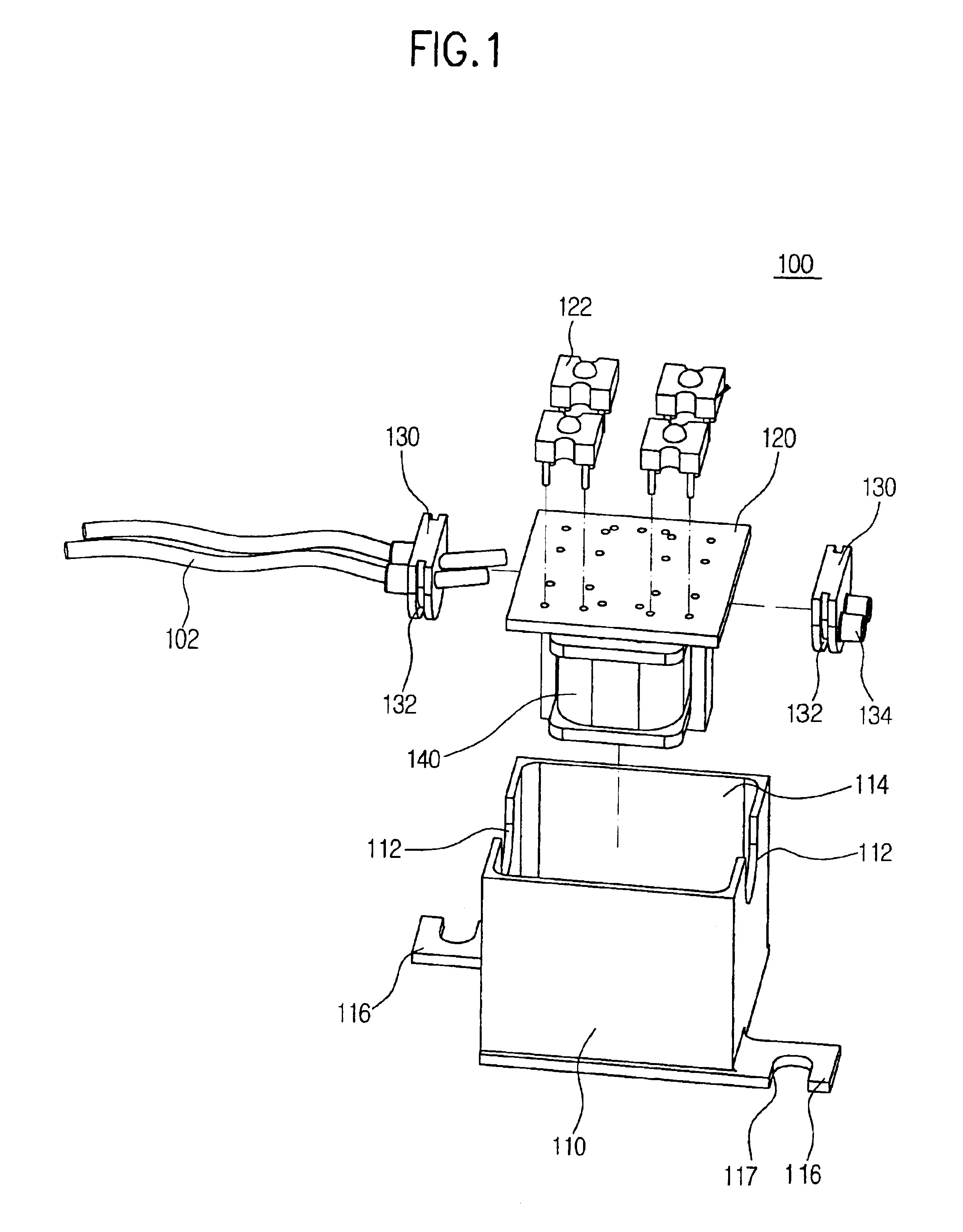
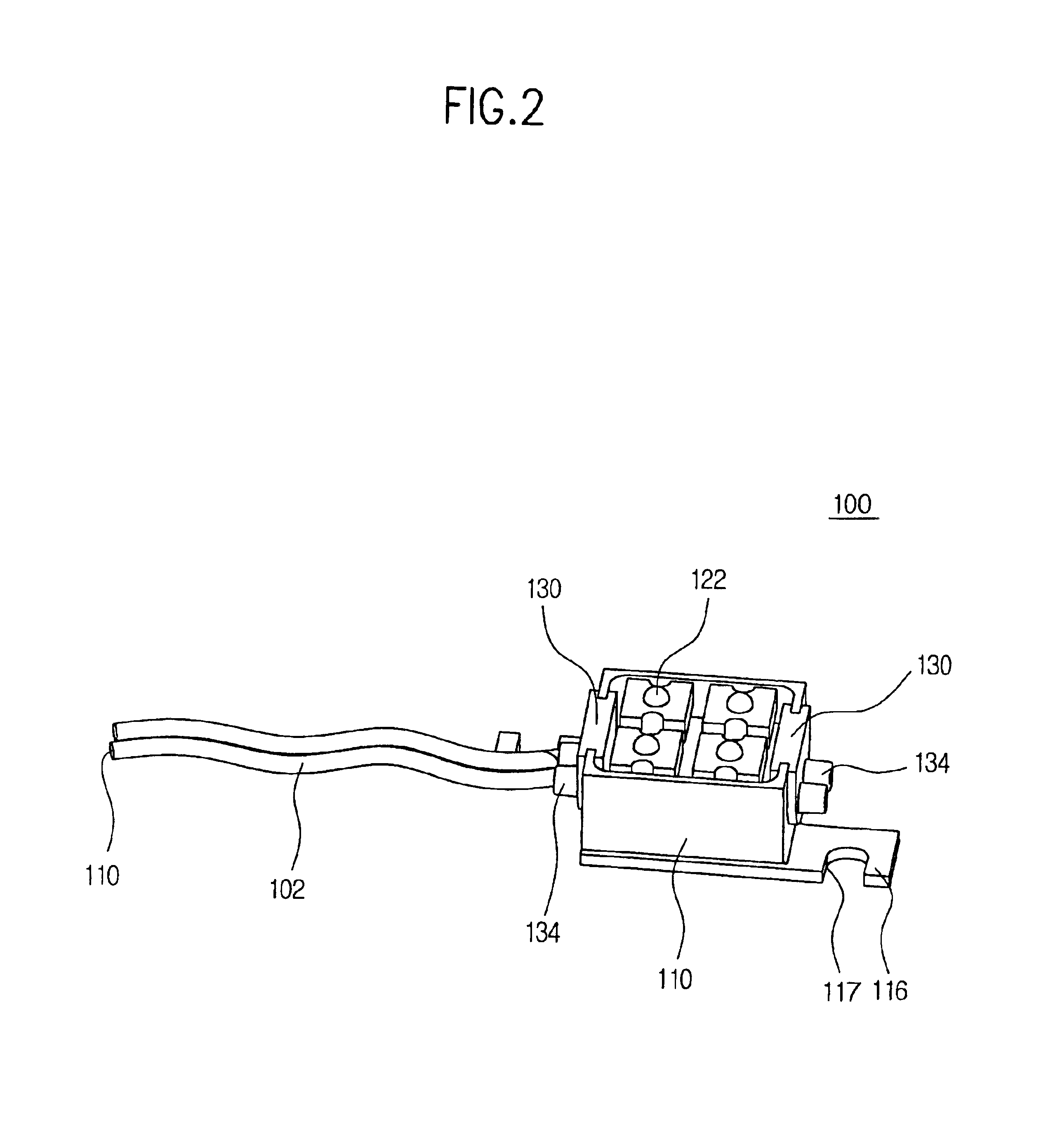
[0024]FIG. 1 shows an exploded state of the light emitting diode assembly for an illuminated sign according to the preferred embodiment of the present invention. Referring to FIG. 1, the light emitting diode assembly 100 is disposed on an illuminated sign 104.

[0025]Referring to FIG. 1, the light emitting diode assembly 100 has a case 110. A receiving chamber is formed at the case 114 and upwardly opened. A coupling recess 112 is formed at upper portions of both of the outside walls of the case 114. Preferably, the coupling recess 112 has a semi-circular shape. A connecting bracket 116 protrudes from lower ends of both sides of the case 110 in an opposite direction. A screw recess 117 is formed in the connecting bracket 116.

[0026]The printed circuit board 120 includes a tr...


PUM


Abstract

The light emitting diode assembly for an illuminated sign is disclosed having an enhanced waterproofs function and an enhanced durability. The light emitting diode assembly includes a case being open upwards, in which a connecting recess is formed on upper portions of both sides of the case. A printed circuit board is installed in the case and being mounted on upper sides of a plurality of light emitting diodes. The hollow cap is coupled in the connecting recess of the case, in which a plurality of wires passes through the cap. A synthetic resin material for covering the printed circuit board, the cap and the light emitting diode, is filled in the case. In this structure, the light emitting diode assembly can prevent the printed circuit board, transformer and the light emitting diode from being damaged by using an epoxy resin.

Description

RELATED APPLICATION(S)[0001]This application claims priority under 35 U.S.C. § 119 or 365 to Korean, Application No. 2003-14096, filed May 7, 2003 and Korean Application No. 2003-21010, filed Apr. 3, 2003. The entire teachings of the above application(s) are incorporated herein by reference.BACKGROUND OF THE INVENTION[0002]1. Field of the Invention[0003]The prevent invention relates to a Light Emitting Diodes (LED), and more particularly to a light emitting diode assembly for an illuminated sign, which can be used as LED modules for various illuminating applications, such as a commercial sign, a street sign, a channel letter sign, etc.[0004]2. Description of the Related Art[0005]Since Light Emitting Diodes (LED) has a relatively low maintenance costs, a relatively high reliability and a relatively long lifetime, it has been used in many applications to replace a conventional incandescent lamp, a fluorescent lamp, a neon tube and fiber optic light sources.[0006]Compared to convention...

Claims


Application Information

Patent Timeline
IPC IPC(8): H05K5/00H05K5/06H05B37/02F21K99/00F21S4/00G09F13/20G09F13/22
CPCF21K9/00G09F13/0404G09F13/22H05K5/0017H05K5/064F21V31/04F21V23/02F21S4/001F21Y2101/02F21V27/02F21S4/10F21Y2115/10
Inventor KIM, SUN-TAI
Owner ATTO DISPLAY
Why Eureka
Try Eureka