Method of waterproofing power circuit section and power module having power circuit section

a technology of power circuit and power module, which is applied in the direction of electrical apparatus casing/cabinet/drawer, dynamo-electric converter control, and connection of coupling devices, etc., can solve the problems of limited connection direction, difficult to form a connector, and insufficient insulation between the external connection terminal and the heat radiating member, etc., to achieve effective waterproofing

Inactive Publication Date: 2005-08-02
WILKINS THOMAS
View PDF18 Cites 47 Cited by
  • Summary
  • Abstract
  • Description
  • Claims
  • Application Information

AI Technical Summary

Benefits of technology

[0016]With this constitution, the extending portion is disposed apart from the heat radiating member owing to the standing portion, whereby it is possible to securely prevent the short-circuit in the extending portion. Since the waterproof resin is filled into the base end portion of the external connection terminal including the standing portion, a waterproof layer with this waterproof resin has a function of the insulating layer, whereby it is possible to securely prevent the short-circuit from occurring near the circuit disposition surface, and keep the secure insulation with the external connection terminal. Also, since the case is assembled with the heat radiating member via the seal member in the form of enclosing the power circuit section inward of the ex

Problems solved by technology

However, in this structure, the connecting direction is limited to the normal direction to the circuit disposition surface.
However, in this case, the external connection terminal is located near the circuit disposition surface of the heat radiating member, bringing about a danger of causing a short-circuit when there is a large current or a large voltage, even though the external connection terminal and the heat radiating member are separated apart.
A

Method used


Image

  • Method of waterproofing power circuit section and power module having power circuit section
  • Method of waterproofing power circuit section and power module having power circuit section
  • Method of waterproofing power circuit section and power module having power circuit section

Examples


Embodiment Construction

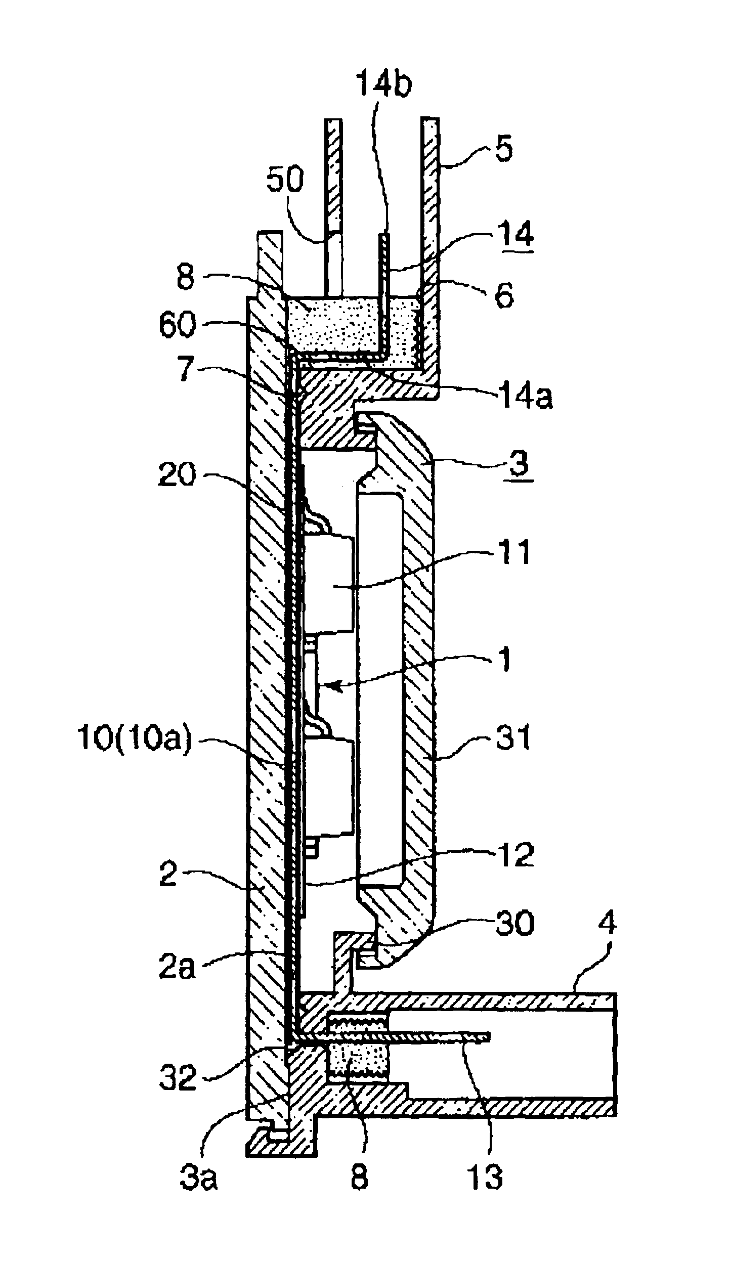
[0022]The preferred embodiments of the present invention will be described below with reference to the accompanying drawings. Herein, described will be a power circuit section for distributing an electric power supplied from a common power source mounted on the vehicle to a plurality of electrical loads. However, the invention is not limited thereto. The invention may be widely applied to various power circuit sections for which heat radiation and waterproofing are required.

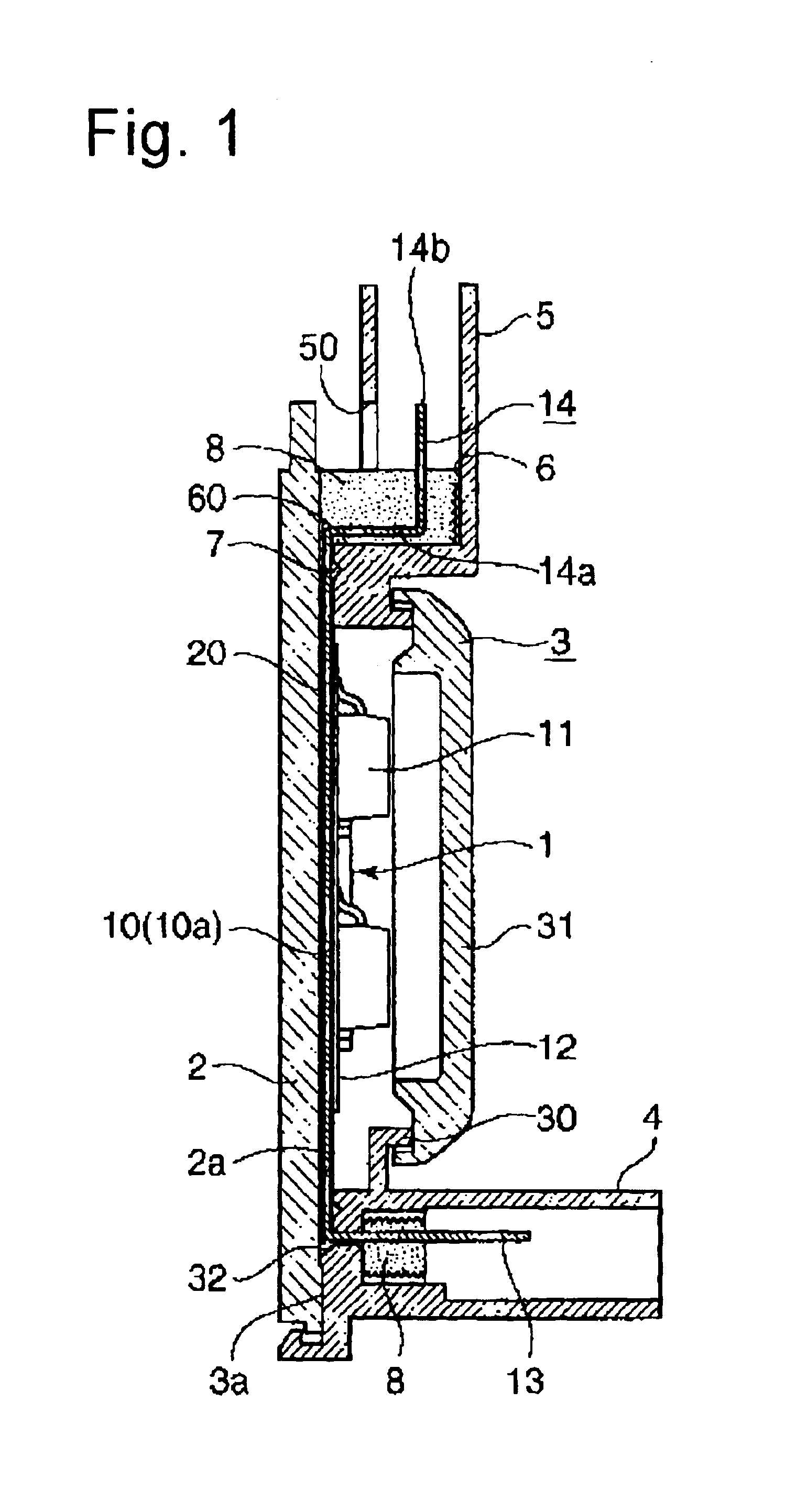
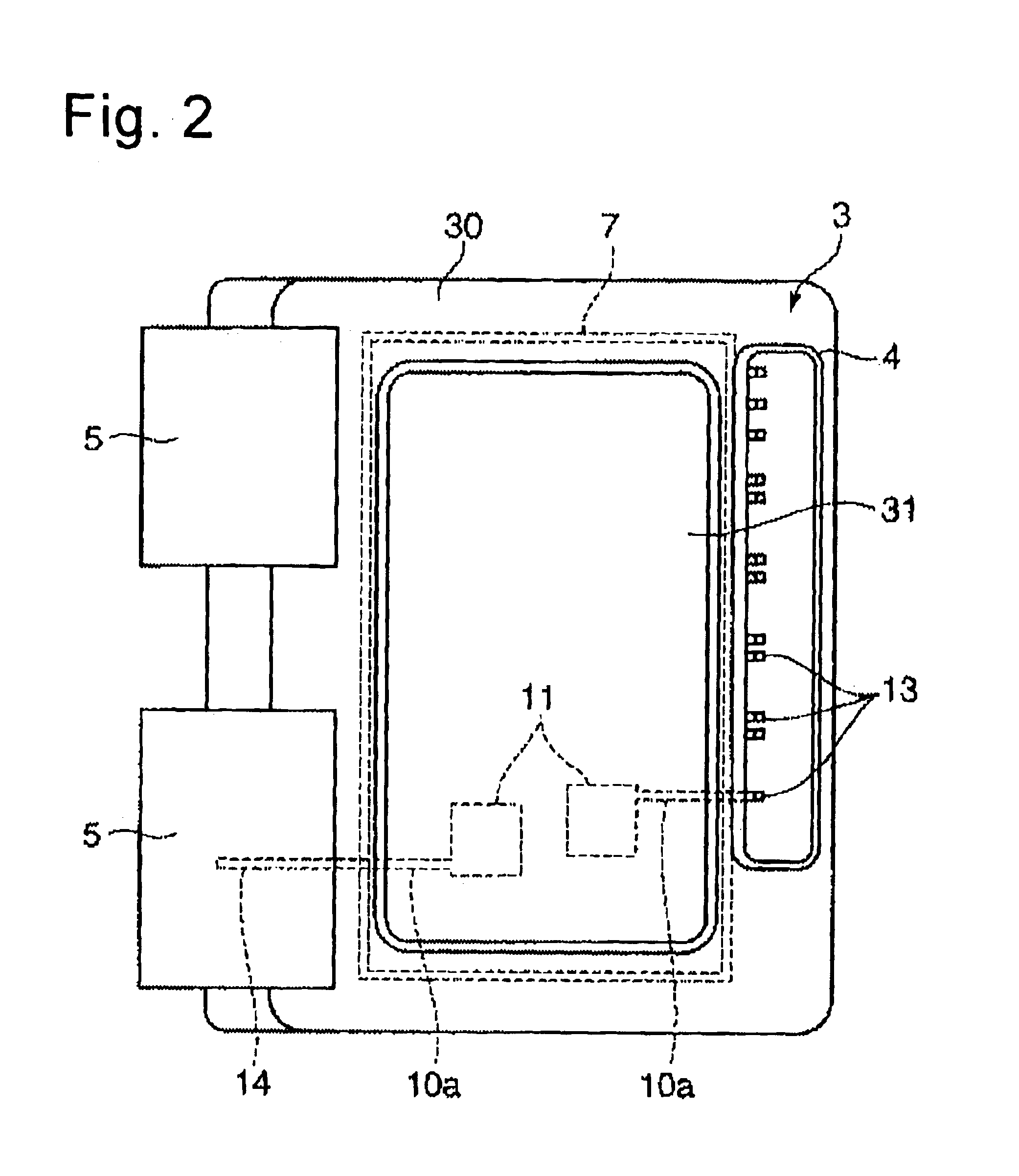
[0023]FIG. 1 is a cross-sectional view showing a power module including a power circuit section, which is waterproofed by a waterproofing method according to an embodiment of the present invention. Also, FIG. 2 is a plan view showing this power module. This power module is mounted on the vehicle vertically, that is, with a left end portion of FIG. 2 placed upwards in this embodiment. However, the power module may be mounted on the vehicle in other directions. In the following explanation, this power module is mou...


PUM


Abstract

A power module includes a heat radiating member, a power circuit section, a resin layer, and a case. The heat radiating member includes a circuit disposition surface. The power circuit section includes an external connection terminal and is disposed on the circuit disposition surface. The resin layer covers a part of the external connection terminal. The case is attached to the heat radiating member. The external connection terminal stands up from the heat radiating member. The case includes a hood, which has an opening at one end portion thereof. The external connection terminal is inserted into the hood. The resin layer prevents liquid from entering through the hood.

Description

BACKGROUND OF THE INVENTION[0001]1. Field of the Invention[0002]The present invention relates to a method for waterproofing a power circuit section including a bus bar and a semiconductor device and disposed on a heat radiating member via an insulating layer, and more particularly to a method for waterproofing a power circuit section for distributing electric power from a common in-vehicle power source to a plurality of electronic units, and a power module having the power circuit section.[0003]2. Description of the Related Art[0004]Conventionally, as means for distributing electric power from the common in-vehicle power source to the plurality of electronic units, an electrical connection box is well-known in which a plurality of bus bar boards are laminated to constitute the power circuit section and into which a fuse and a relay switch are incorporated.[0005]Generally, such electrical connection box has the power circuit section accommodated within a case including an upper case ...

Claims


Application Information

Patent Timeline
IPC IPC(8): H05K5/00H05K5/06H01R13/52H01L25/07H01L25/18
CPCH05K5/062H05K7/20854H01R13/5216
Inventor KAWAKITA, SHINJIONIZUKA, TAKAHIRO
Owner WILKINS THOMAS
Why Eureka
Try Eureka