Method of using electrical and acoustic anisotropy measurements for fracture identification

a technology of electrical and acoustic anisotropy and fracture identification, which is applied in the field of interpretation of measurements made, can solve the problems of inability to distinguish between anisotropy caused by stress and anisotropy caused by fracture, and difficulty in correlated surface seismic measurements of azimuthal anisotropy with specific reservoir intervals

Inactive Publication Date: 2005-08-02
BAKER HUGHES INC
View PDF13 Cites 25 Cited by
  • Summary
  • Abstract
  • Description
  • Claims
  • Application Information

AI Technical Summary

Problems solved by technology

In addition, the fractures also contribute significantly to the permeability of the reservoir.
Seismic data has a resolution of the order of tens of meters and it is difficult to correlate surface seismic measurements of azimuthal anisotropy with specific reservoir intervals.
The stripping techniques have a large amount of uncertainty associated with the estimate of the principal directions of shear wave anisotropy.
A drawback of shear wave birefringence measurements is their inability to distinguish between anisotropy caused by stress and anisotropy caused by fracturing.
The tool of Bittar uses transmitter antennas with the coil axis parallel to the tool and the borehole and is not designed to detect the smaller effects due to any oriented fracturing in the formation.
Heavy muds may induce fractures when the mud pressure exceeds the rock strength.

Method used


Image

  • Method of using electrical and acoustic anisotropy measurements for fracture identification
  • Method of using electrical and acoustic anisotropy measurements for fracture identification
  • Method of using electrical and acoustic anisotropy measurements for fracture identification

Examples


Embodiment Construction

[0037]In the method of the present invention, a cross-dipole logging tool is used to determine the propagation velocities of shear waves generated by transmitters with two different (preferably orthogonal) polarizations and recorded by at least two receivers with preferably orthogonal orientation. By using prior art methods such as that described by Tang, the principal directions of azimuthal anisotropy for shear waves is determined along with the two shear velocities. As noted in the background of the invention, there is no guarantee that the borehole axis would be normal to the bedding plane. However, those versed in the art would recognize that for deviations from normality of up to 10°, the effects of dip would be small and the prior art rotation method would give reasonably good estimates of the principal directions of azimuthal anisotropy.

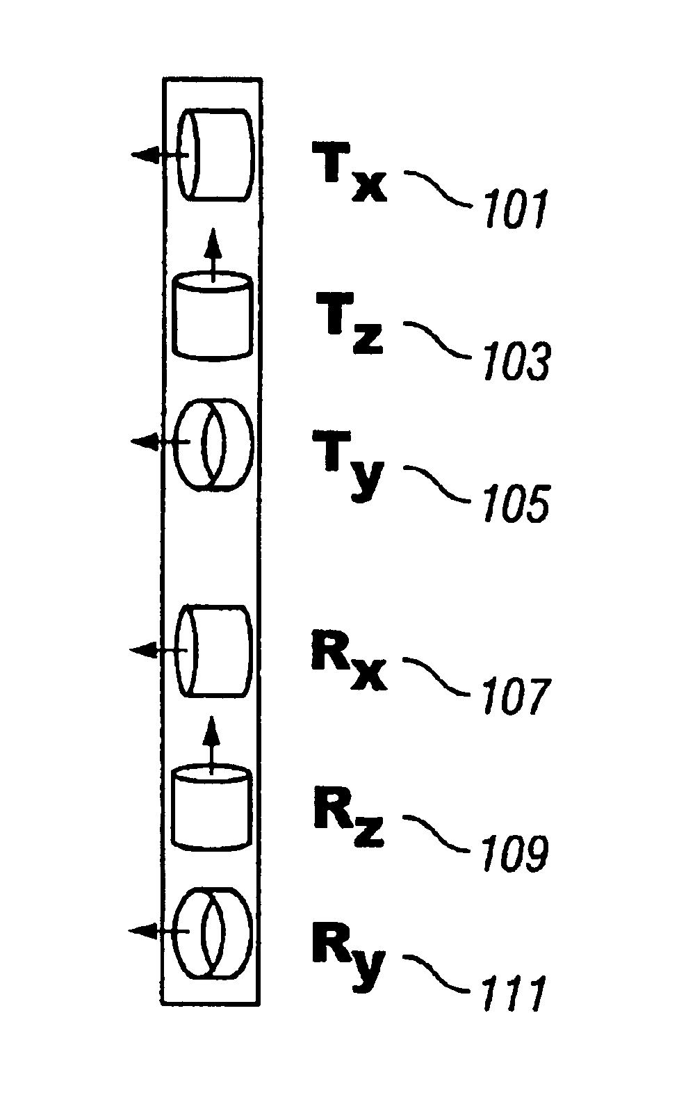
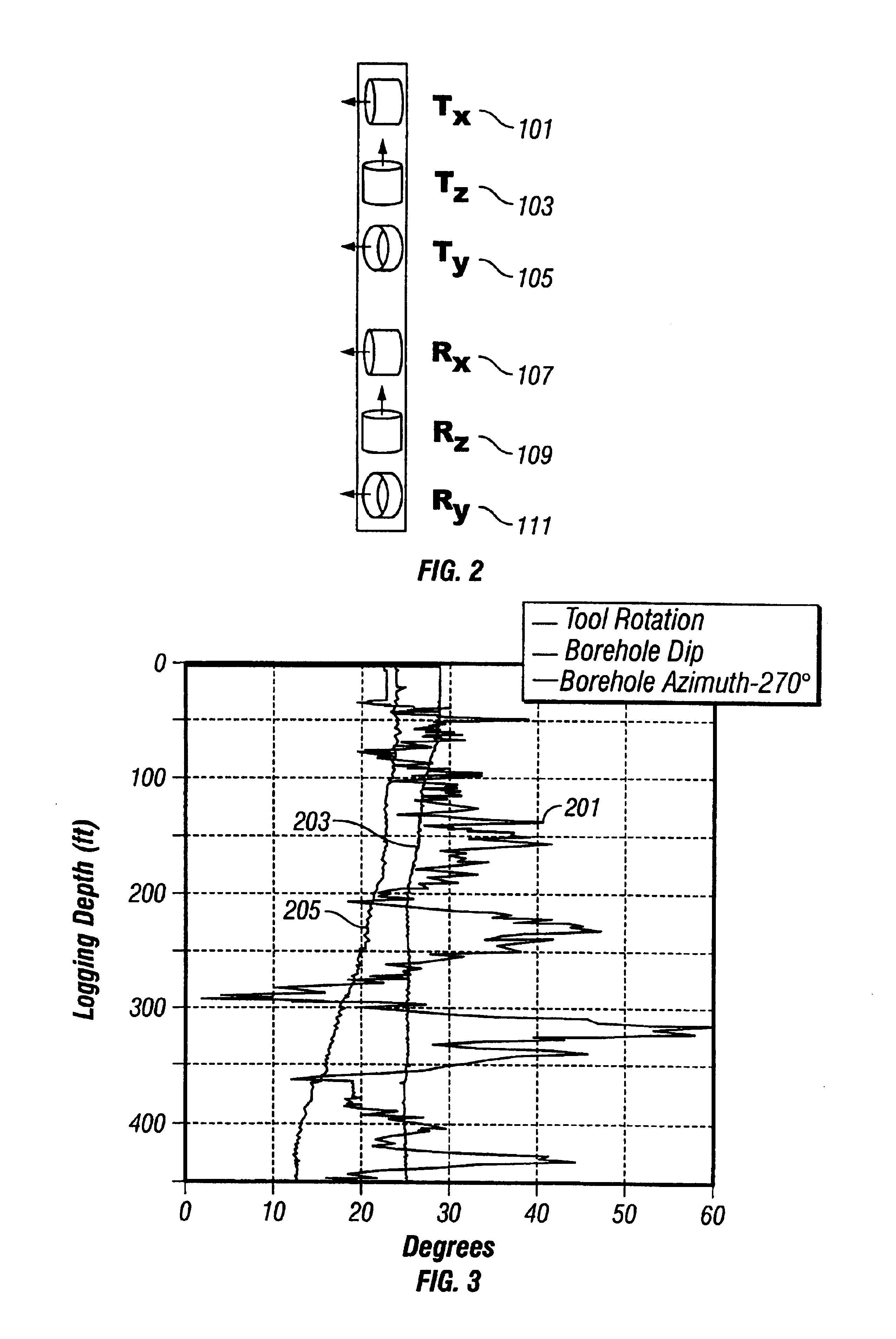
[0038]Referring to FIG. 2, the configuration of transmitter and receiver coils in a preferred embodiment of the 3DEX induction logging instr...


PUM


Abstract

Measurements made by a cross-dipole acoustic logging tool in a borehole are processed to determine the principal directions of azimuthal anisotropy of a subsurface formation. Measurements indicative of azimuthal resistivity variations are also made with a multicomponent induction logging tool. These electrical measurements are processed using the principal direction determined from acoustic measurements to give an estimate of azimuthal resistivity variations. Based on modeling results, azimuthal resistivity variations are interpreted to estimate a fracture depth in the rock for known fluids therein.

Description

CROSS REFERENCES TO RELATED APPLICATIONS[0001]This application claims priority from U.S. Provisional Patent Application Ser. No. 60 / 341,595 filed on Dec. 13, 2001.BACKGROUND OF THE INVENTION[0002]1. Field of the Invention[0003]The invention is related generally to the field of interpretation of measurements made by well logging instruments for the purpose of determining the properties of earth formations. More specifically, the invention is related to a method for identification of the extent and direction of fracturing in subsurface formations.[0004]2. Background of the Art[0005]A significant number of hydrocarbon reservoirs comprise fractured rocks wherein the fracture porosity makes up a large portion of the fluid-filled space. In addition, the fractures also contribute significantly to the permeability of the reservoir. Identification of the direction and extent of fracturing is important in reservoir development for two main reasons.[0006]An important reason for identification ...

Claims


Application Information

Patent Timeline
Patent Type & Authority Patents(United States)
IPC IPC(8): G01V1/48G01V1/40G01V11/00
CPCG01V1/48G01V11/00
Inventor KRIEGSHAUSER, BERTHOLDFANINI, OTTO N.MOLLISON, RICHARD A.YU, LIMINGWANG, TSILITANG, XIAO MING
Owner BAKER HUGHES INC
Why Eureka
Try Eureka