Modular bus air conditioning system

a bus and air conditioning technology, applied in refrigeration machines, light and heating equipment, transportation and packaging, etc., can solve the problems of increasing installation and maintenance costs, affecting the degree of air conditioning, and the speed of compressors, etc., and achieve the effect of low cos

Active Publication Date: 2005-08-09
CARRIER CORP
View PDF3 Cites 36 Cited by
  • Summary
  • Abstract
  • Description
  • Claims
  • Application Information

AI Technical Summary

Benefits of technology

[0019]In accordance with another aspect of the invention, rather than a large single air conditioning unit, a plurality of relatively small identical modules can be installed on the roof of a bus, with each being capable of operating independently of the others so as to allow for the relatively low cost mass production of identical standardized units and also provide for a limp home capability in the event of failure of one or more units.

Problems solved by technology

This, of course, requires rather extensive piping between the engine compartment and the air conditioning unit, thereby increasing installation and maintenance costs.
Another problem with such existing systems is that the speed that the compressor is driven is dependent on the speed in which the drive engine is running.
Thus, when the drive engine is idling in a parking lot, for example, the compressor is running at a relatively slow speed which may not be sufficient to provide the desired degree of air conditioning.
Others problems associated with such a motor driven compressor system is that the open drive compressor needs a shaft seal and a mechanical clutch, both of which are subject to maintenance problems.
In general, DC motors are not as reliable as AC motors since they have brushes that wear out, and brushless motors are relatively expensive.
As a result, the manufacturing and installation costs, and sustaining engineering resources that are necessary in order to properly maintain and service these units, are relatively high.
Also associated with the existing bus air conditioning systems is the problem of a component failure causing a complete loss of the air conditioning capacity.
That is, with a single large unit as is now customary, failure of that unit such as, for example, a leaking hose causing loss of refrigerant, an electrical failure leading to inoperation of one of the components such as a fan, or a compressor failure, the entire unit is inoperable and no air conditioning can be provided to the unit.

Method used


Image

  • Modular bus air conditioning system
  • Modular bus air conditioning system
  • Modular bus air conditioning system

Examples


Embodiment Construction

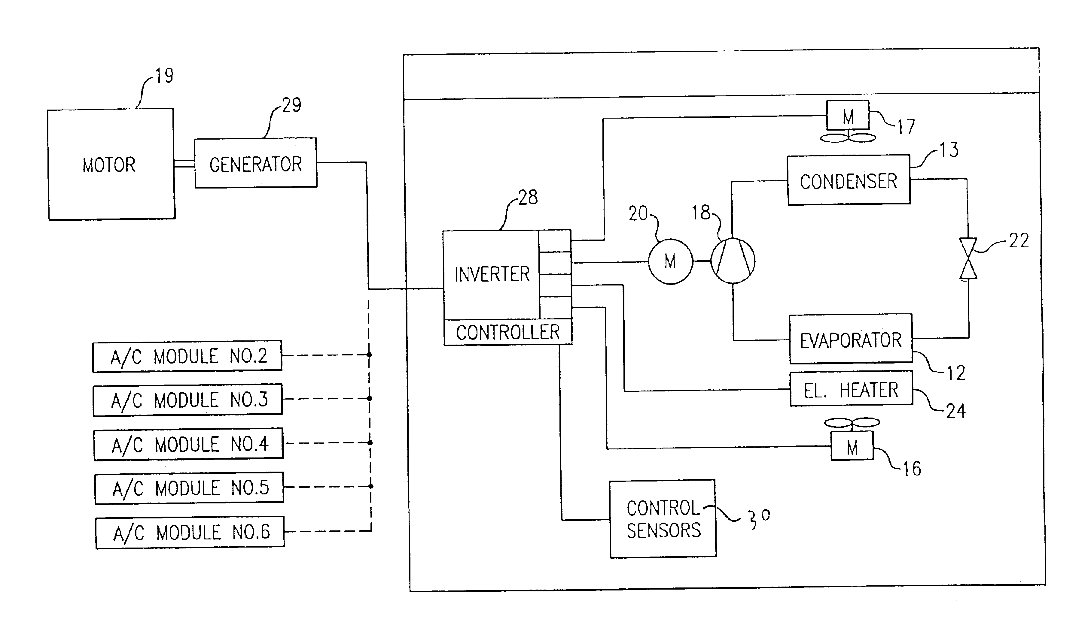
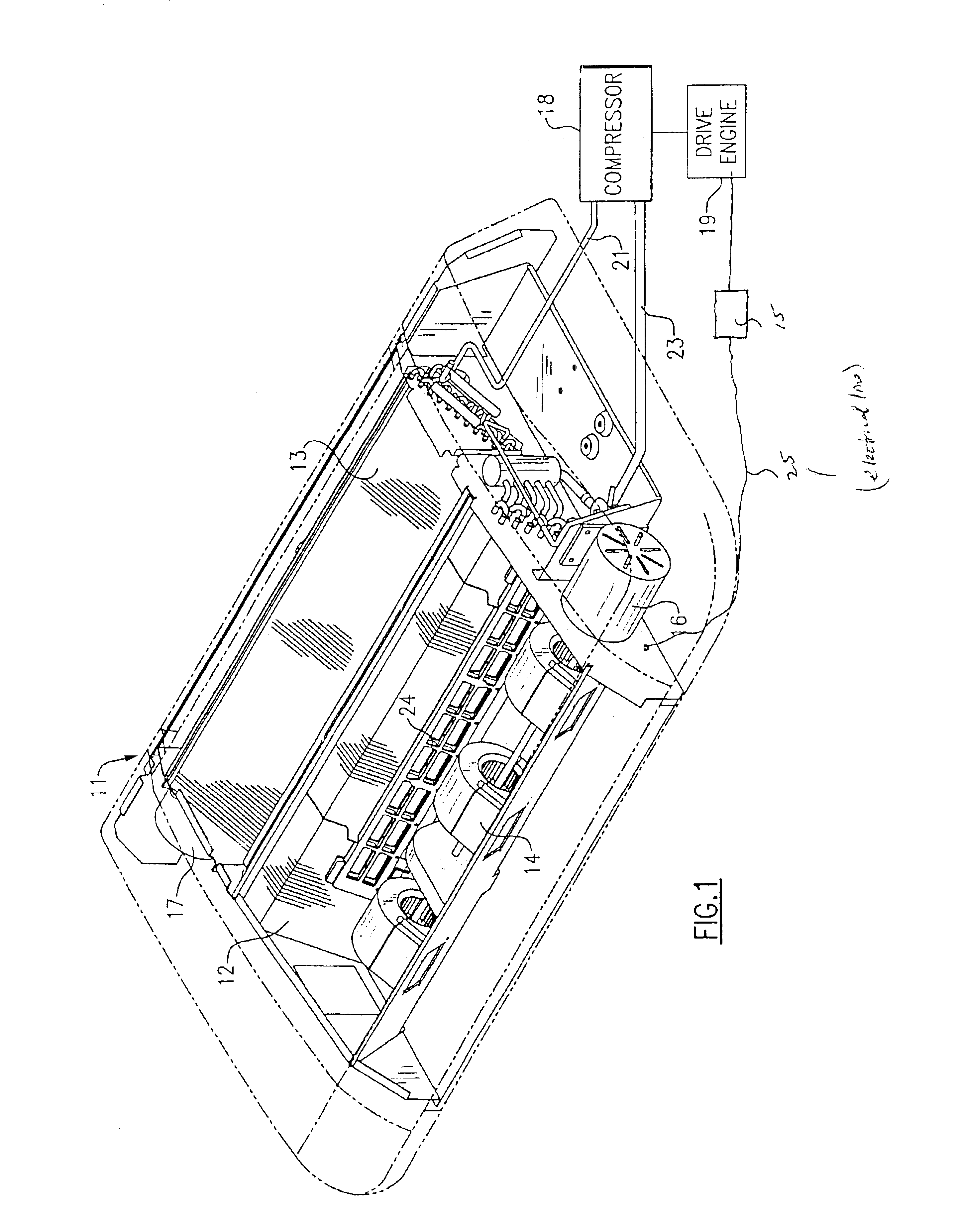
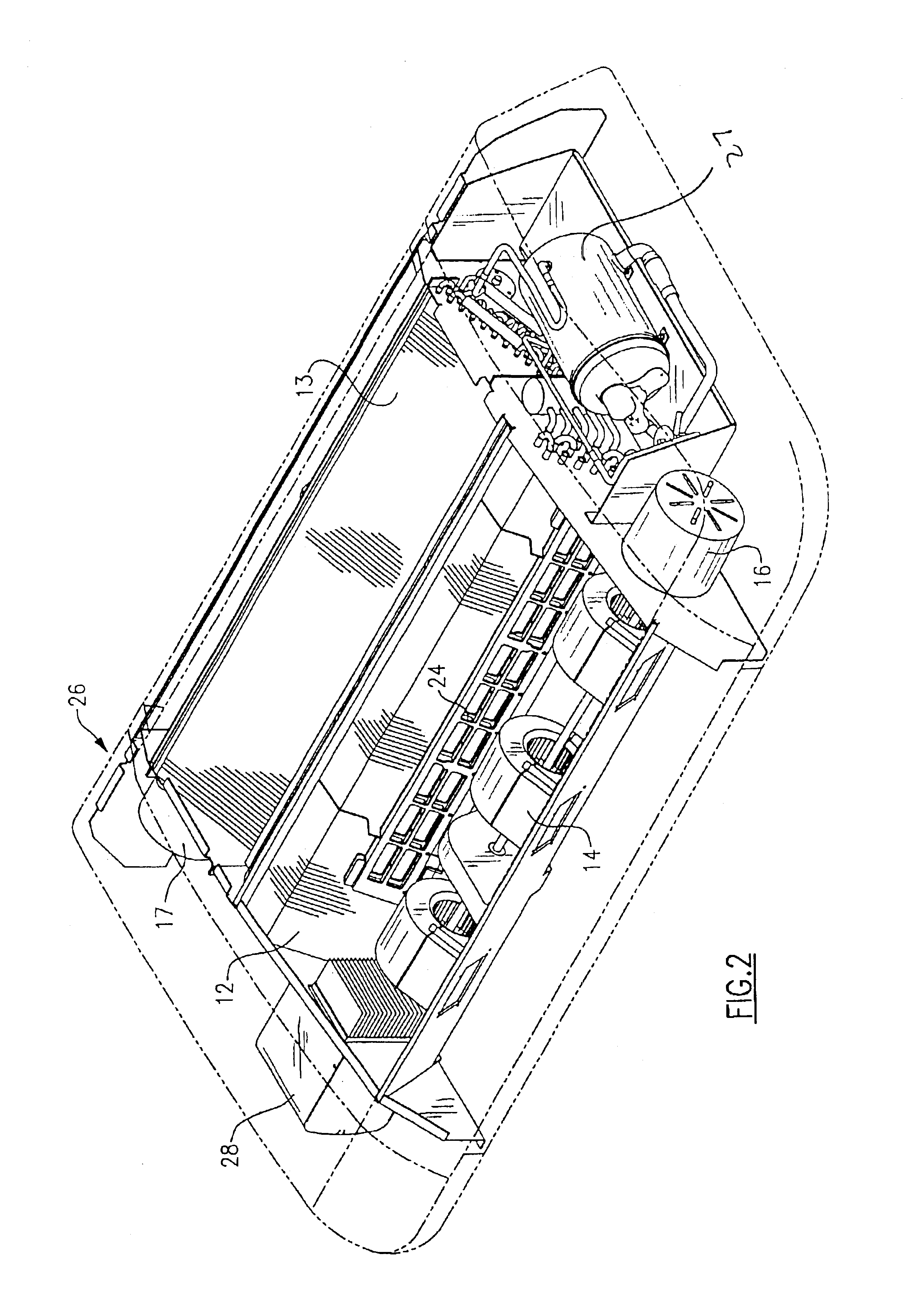
[0034]FIG. 1 shows a module 11 with the cover removed to show the various components including an evaporator coil 12, a condenser coil 13, a plurality of evaporator blowers 14 and associated drive motors 16, and a condenser fan motor 17 for driving a condenser fan (see FIG. 3).

[0035]Outside the module 11 is a compressor 18 which is driven by a motor drive 19 to pump refrigerant from the compressor 18 through refrigerant line 21 to the condenser coil 13 and eventually to the evaporator coil 12 by way of an expansion valve 22 (see FIG. 3). The refrigerant vapor then passes back to the compressor 18 by way of refrigerant line 23.

[0036]The drive engine 19 is also operatively connected to an electrical generator 15, (or alternator, if desired) for providing electrical power to the module by way of line 25.

[0037]Also shown in FIG. 1 is an electrical resistance heater 24 which is downstream of the evaporator coil 12 such that, for periods of heating, the air is drawn by the evaporator blow...


PUM


Abstract

A module for a bus rooftop air conditioner is self contained in that it has all the necessary components including a compressor, if desired, which when supplied with electrical power, can provide conditioned air to the passenger compartment of a bus. In addition, an electrically powered heater is provided in the air flowstream such that heated air can also be supplied to the passenger compartment when desired. Multiple units provide for incremental capacity requirements to be met as well as limp home capabilities.

Description

CROSS REFERENCE TO RELATED APPLICATIONS[0001]This application is related to the following pending applications being concurrently filed herewith and assigned to the assignee of the present invention:[0002]Our DocketTitleNo.:Modular Rooftop Air Conditioner for a Bus210_546Modular Bus Air Conditioning System210_545Supply Air Blower Design in Bus Air Conditioning Units210_549Bus Rooftop Condenser Fan210_550Method and Apparatus for Refreshing Air in a Bustop Air210_548ConditionerCoil Housing Design for a Bus Air Conditioning Unit210_547Integrated Air Conditioning Module for a Bus210_558Fresh Air Intake Filter and Multi Function Grill210_554Integrated Air Conditioning Module for a Bus210_557Modular Air Conditioner for a Bus210_561Modular Air Conditioner for a Bus Rooftop210_562Evaporator Section for a Modular Bus Air Conditioner210_564Wide Evaporator Section for a Modular Bus Air210_565ConditionerCondensate Pump for Rooftop Air Conditioning Unit210_568Condensate Removal System Rooftop Ai...

Claims


Application Information

Patent Timeline
Patent Type & Authority Patents(United States)
IPC IPC(8): B60H1/00
CPCB60H1/00371B60H1/00428B60H1/00542B60H2001/00235B60H2001/00128Y02T10/88B60H1/039B60H1/00535
Inventor HILLE, ANDREASREIMANN, ROBERT C.CZECHOWICZ, BELIN
Owner CARRIER CORP
Why Eureka
Try Eureka