
Well-water-type liquid cooling and heating resource system

a technology of liquid cooling and heating resources, applied in the field of energy resource systems, can solve the problems of high cost, high cost, and large storage of low-level cold and heat resources, and achieve the effects of reducing the investment of wells, no toxic and harmful materials, and no pollution

Inactive Publication Date: 2005-08-09
EVER SOURCE SCI & TECH DEV GRP CO LTD
View PDF9 Cites 6 Cited by
  • Summary
  • Abstract
  • Description
  • Claims
  • Application Information

AI Technical Summary

Benefits of technology

"The present invention provides a well-water-type liquid cooling and heating resource system that overcomes shortages of conventional systems. The system uses non-pollution and lower cost resources and has the merits of lower cost and no pollution. The system includes a well, a suction pump, an energy lift device, and a discharge pump. The energy lift device consists of a heating cycle and a heat-exchanging cycle. The system also includes two two-position-four-way valves and a working medium or antifreeze solution. The system can provide cooling or heating as needed and does not produce toxic or harmful materials during operation. The system uses the same well for both supplying and returning water, reducing the investment cost. The system also allows for water returning when there is obstruction and enables the water to be returned under compression."

Problems solved by technology

It is known that not only do coal, gas and oil have limited reserves, but produce massive ash, dust or exhaust gas while / after their combustion, not only polluting the environment, but transforming the atmosphere properties, thus resulting in greenhouse effect which warms the earth and then melts glaciers and rises the ocean level and etc.
Energy used in conventional refrigerating systems is electricity, which costs higher, and an amount of it are also generated from burning fuels like coal, gas or oil etc, therefore the same problems caused by combusting those fuels to the environment happen here again.
However, massive low level cold and heat resources are stored in underground water.
Consequently, the cost is high.

Method used


Image

  • Well-water-type liquid cooling and heating resource system
  • Well-water-type liquid cooling and heating resource system
  • Well-water-type liquid cooling and heating resource system

Examples


Embodiment Construction

[0014]Referring to the drawings, the well-water-type liquid cooling and heating resource system of the present invention shall be further described as follows.

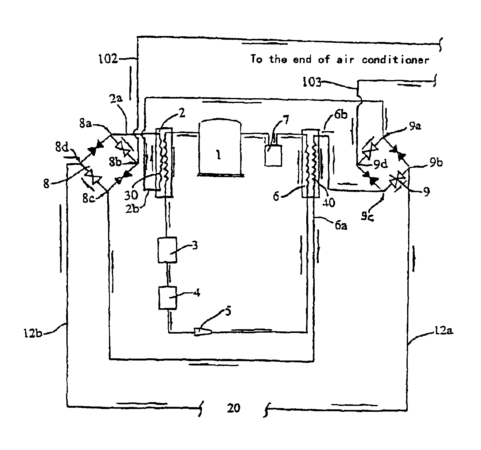
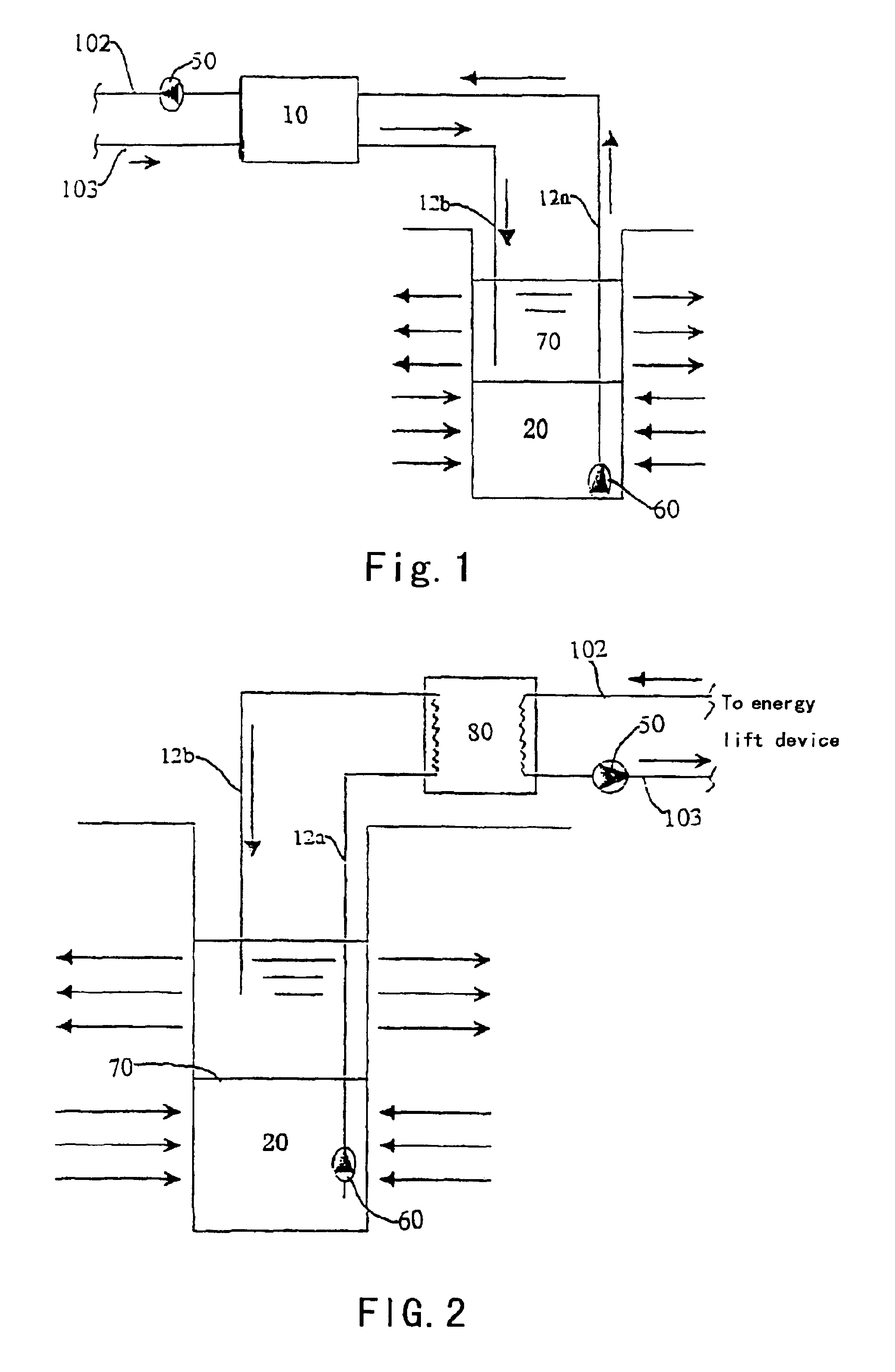
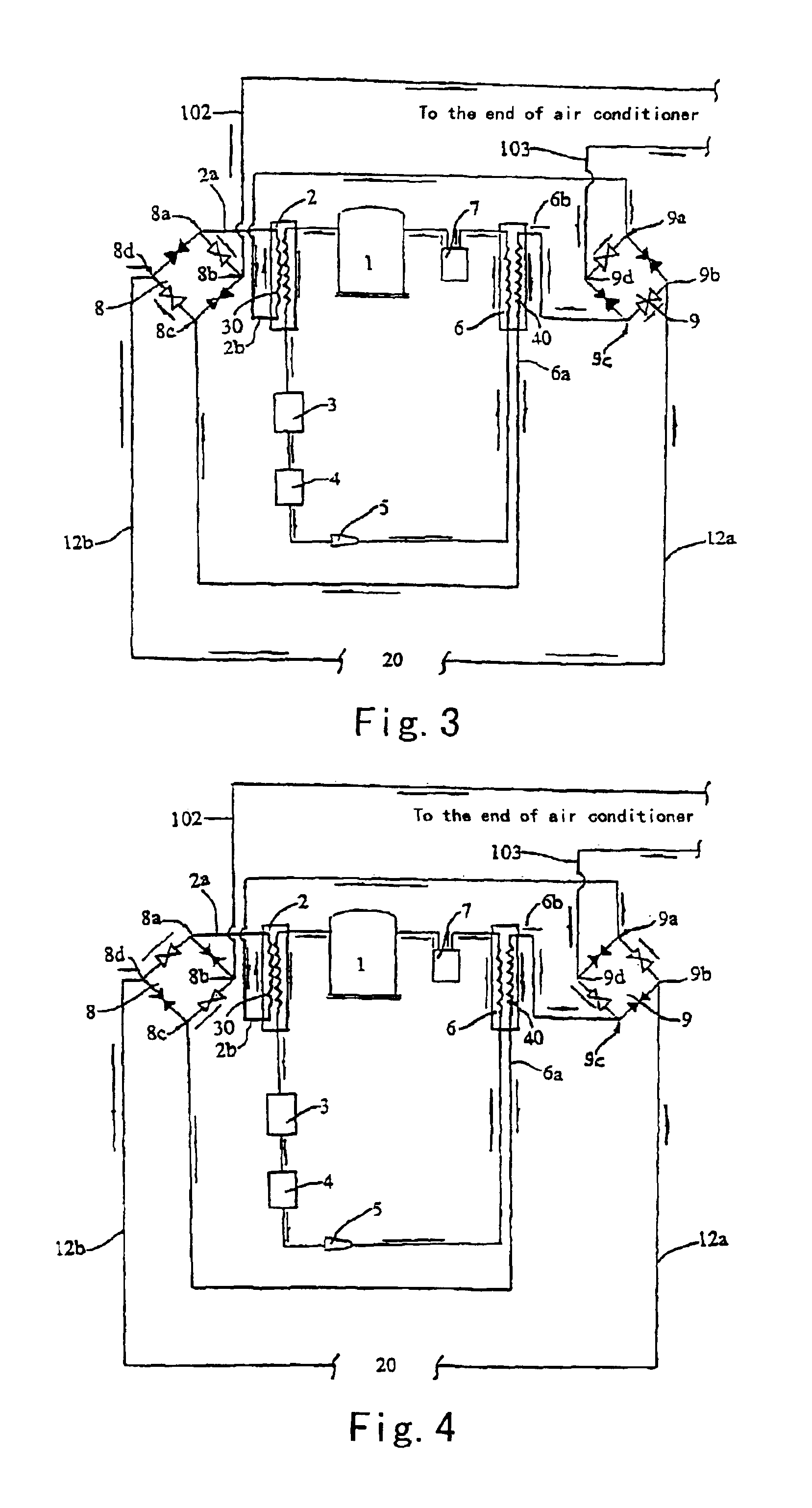
[0015]As shown in FIG. 1, the invention's well-water-type liquid cooling and heating resource system comprises, a well 20, an energy lift device 10, a discharge pump 50 and a suction pump 60 connected together by the conduits. Well 20 enables to provide constant-temperature well-water from low level cold and heat resources at about 15° C., the discharging tube 12a, returning tube 12b is connected respectively to the liquid inlet tube and the returning tube of energy lift device. The suction pump 60 is mounted on the lower portion of the well 20. The discharging tube 102 of energy lift device 10 is connected to an air conditioner (not shown). The discharge pump 50 is mounted on the discharging tube 102, and the returning tube 103 of the air conditioner is connected to liquid inlet tube 2b (FIG. 3) of heat exchanging pipeline 30...


PUM


Abstract

A well-water-type liquid cooling and heating resource system of the present invention, comprises a well, an energy lift device, a discharging pump and a suction pump sequentially connected by conduits. The well is separated into an upper portion and a lower portion by a baffle plate, and can supply constant temperature water at about 15° C. using as the low level cold and heat resources. The discharging tube and returning tube of the well is connected respectively with a liquid inlet tube and returning tube of the energy lift device. The suction pump is mounted at the lower portion of the well or on the baffle plate. The discharging tube of energy lift device, which is equipped with a discharge pump, is connected to a load such as an air conditioner. The load such as the air conditioner's returning tube is connected with the liquid inlet tube of a heat-exchanging pipeline coupling with the condenser of the energy lift device. The system costs lower and has no pollution.

Description

FIELD OF THE INVENTION[0001]The present invention relates to an energy resource system, in particular to a well-water-type liquid cooling and heating resource system.BACKGROUND OF THE INVENTION[0002]At present, common heat supply system employs coal, gas or oil as main energy resources. It is known that not only do coal, gas and oil have limited reserves, but produce massive ash, dust or exhaust gas while / after their combustion, not only polluting the environment, but transforming the atmosphere properties, thus resulting in greenhouse effect which warms the earth and then melts glaciers and rises the ocean level and etc. Energy used in conventional refrigerating systems is electricity, which costs higher, and an amount of it are also generated from burning fuels like coal, gas or oil etc, therefore the same problems caused by combusting those fuels to the environment happen here again. However, massive low level cold and heat resources are stored in underground water. A water-water...

Claims


Application Information

Patent Timeline
Patent Type & Authority Patents(United States)
IPC IPC(8): F24J3/00F24J3/08F25B30/06F25B30/00
CPCF24J3/085F25B30/06Y02E10/14F24T10/20Y02E10/10
Inventor XU, SHENGHENG
Owner EVER SOURCE SCI & TECH DEV GRP CO LTD
Learn More