Hand held stent crimping apparatus and method

a crimping apparatus and stent technology, applied in forging/pressing/hammering apparatus, prosthesis, blood vessels, etc., can solve the problems of stent or other article compression and closure of center apertur

Inactive Publication Date: 2005-08-09
MACHINE SOLUTIONS
View PDF11 Cites 77 Cited by
  • Summary
  • Abstract
  • Description
  • Claims
  • Application Information

AI Technical Summary

Problems solved by technology

Actuation of the handle rotates the drive hub, which causes the segments to move and pivot, resulting in closure of the center aperture and compression of the stent or other article.

Method used


Image

  • Hand held stent crimping apparatus and method
  • Hand held stent crimping apparatus and method
  • Hand held stent crimping apparatus and method

Examples


Embodiment Construction

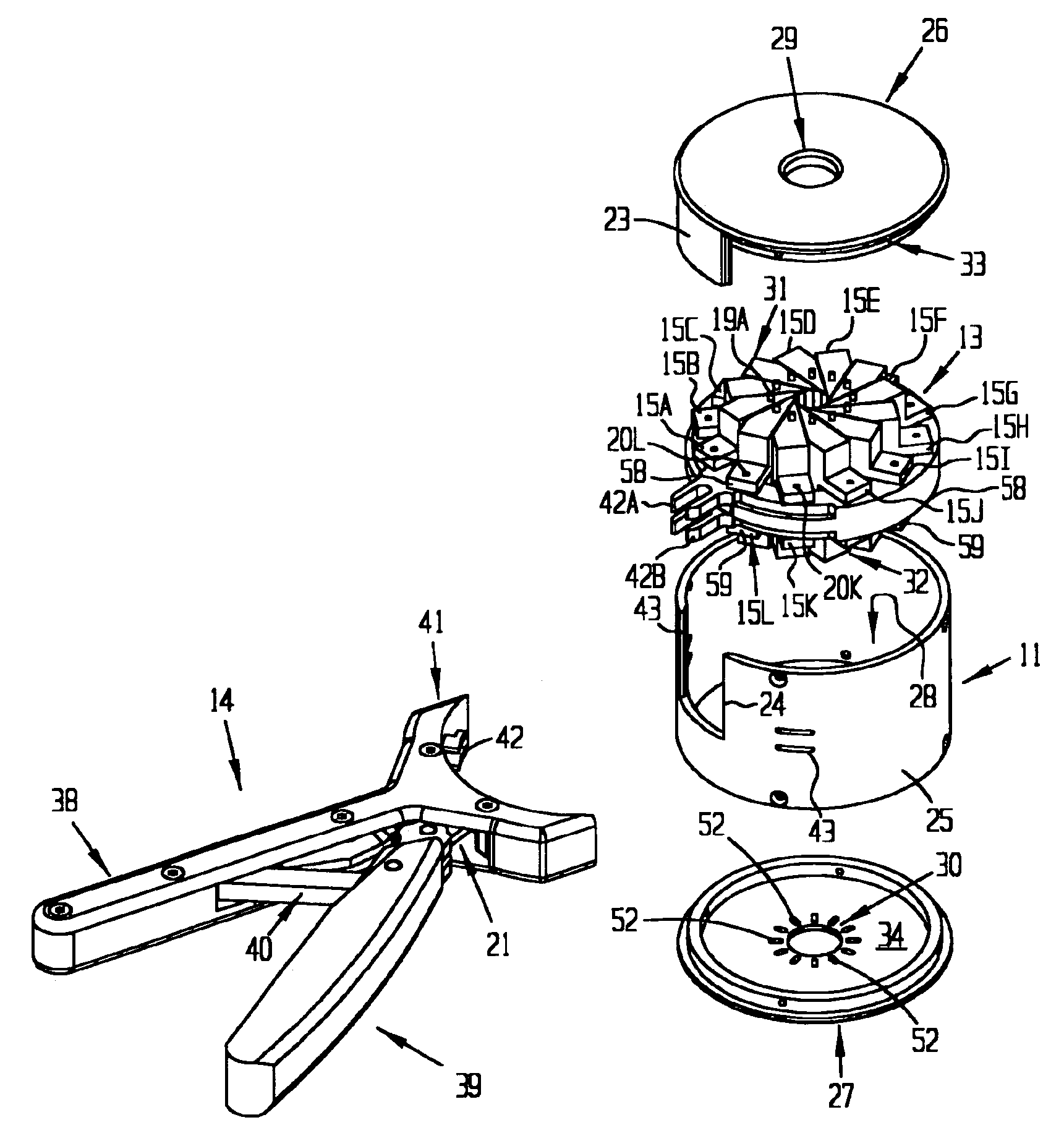
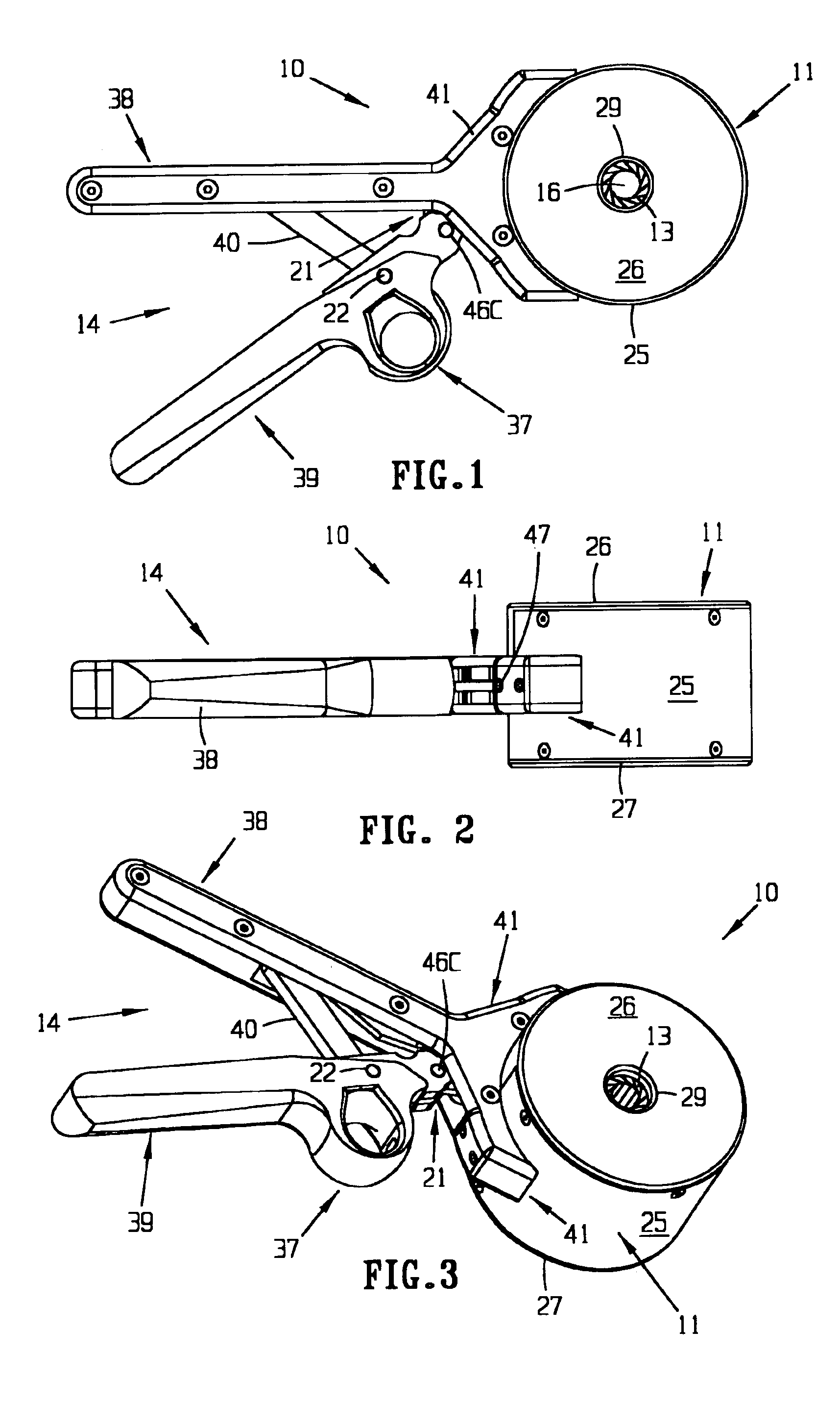
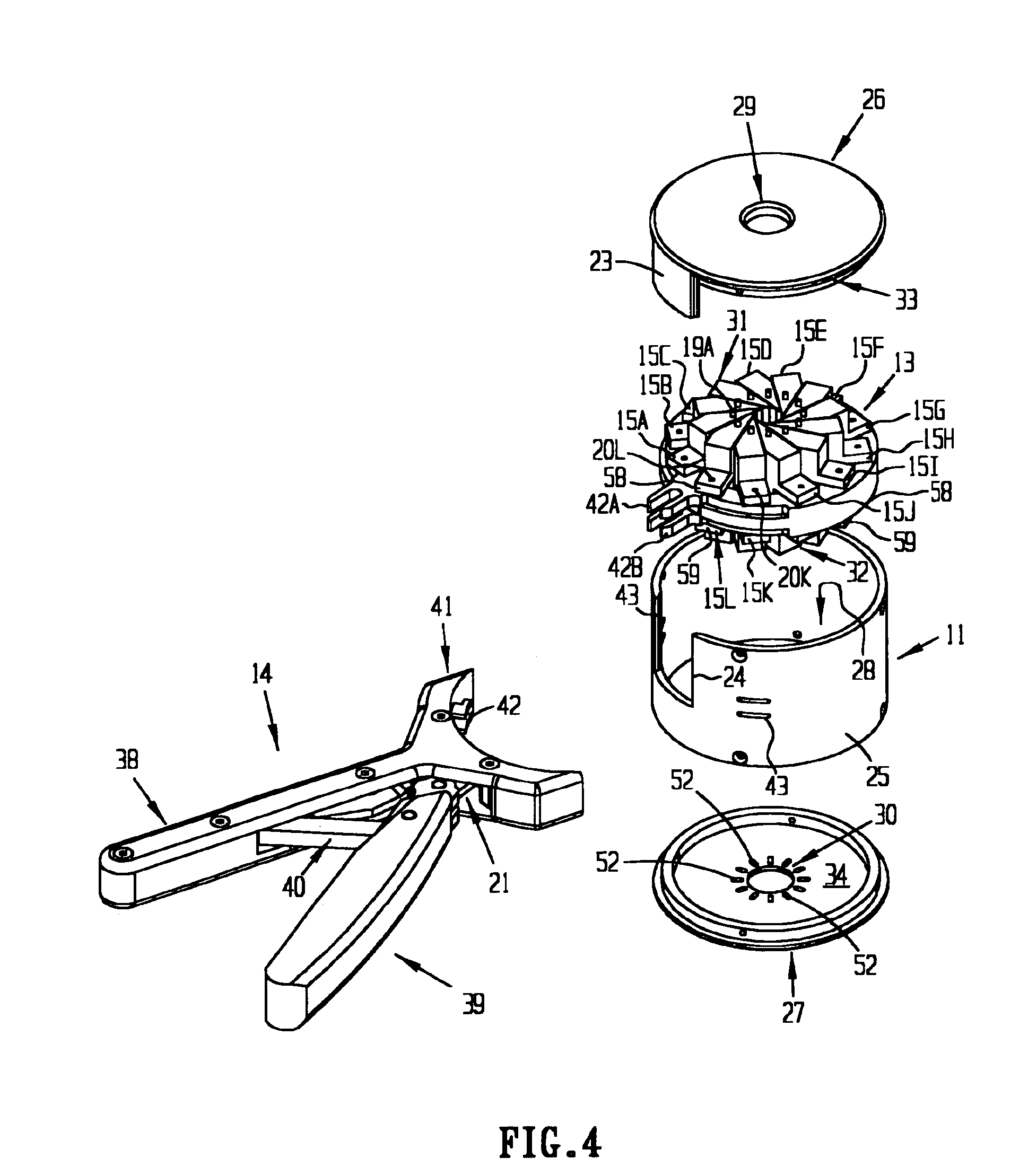
[0044]The hand held stent crimping device and method is suitable to uniformly crimp a balloon expandable or self-expanding metal or non-metallic stents or sent grafts. A crimped stent includes a core such as a balloon catheter and a sheath. The stent is uniformly crimped to the collapsed balloon along the length, preferably within a diameter tolerance of 0.005 inches. The apparatus and methods of the invention may also be used or adapted for use in securely gripping, holding and / or selectively radially compressing other articles. The apparatus and methods are also useable or adaptable for use in crease and / or fold structures such as balloons, to form a wide variety of radial compression devices (such as within a machining center so that the machinists will not have to replace collets), and to form or create a stent retention mechanism that retains the stent without applying radial forces against the balloon, thus enabling the balloon or sheath to be retracted.

[0045]Referring to FIGS...


PUM

PropertyMeasurementUnit
diametersaaaaaaaaaa
diameteraaaaaaaaaa
lengthaaaaaaaaaa

Abstract

A hand actuatable apparatus and method for crimping a stent or processing other articles by segmental radial compression. The apparatus includes a stationary base housing; a rotatable drive hub which is moveable in relation to the base housing; a crimping head communicatively coupled to the base housing and to the drive hub; and an actuator handle connected to the base housing and to the drive hub. The crimping head includes a plurality of segments oriented about a center aperture which receives a stent or article to be compressed. The segments each have a proximal end and an angled distal end with at least one angled side face terminating in an edge of a predetermined length and defining the center aperture. Actuation of the handle rotates the drive hub, which causes the segments to move and pivot, resulting in closure of the center aperture and compression of the stent or other article.

Description

CROSS-REFERENCE TO RELATED APPLICATIONS, IF ANY[0001]This application claims the benefit under 35 U.S.C. §119(e) of U.S. Provisional Patent Application Ser. No. 60 / 407,403, filed Aug. 31, 2002, which is hereby incorporated by reference.37 C.F.R. §1.71(E) AUTHORIZATION[0002]A portion of the disclosure of this patent document contains material which is subject to copyright protection. The copyright owner has no objection to the facsimile reproduction by anyone of the patent document or the patent disclosure, as it appears in the Patent and Trademark Office patent file or records, but otherwise reserves all copyright rights whatsoever.STATEMENT REGARDING FEDERALLY SPONSORED RESEARCH OR DEVELOPMENT[0003]Not applicable.REFERENCE TO A MICROFICHE APPENDIX, IF ANY[0004]Not applicable.BACKGROUND OF THE INVENTION[0005]1. Field of the Invention[0006]The present invention relates, generally, to medical devices and medical device manufacturing apparatus and methods. Additionally, the invention r...

Claims


Application Information

Patent Timeline
Patent Type & Authority Patents(United States)
IPC IPC(8): B21D39/04B23P11/00A61BA61F2/06A61F2/84B21D41/04
CPCA61F2/95B21D41/04B21D39/04A61F2/2412A61F2002/9522Y10T29/53996Y10T29/49908A61F2/9522A61F2/9524
Inventor MOTSENBOCKER, THOMAS
Owner MACHINE SOLUTIONS
Why Eureka
Try Eureka