Ultrasonic fuel-gauging system

a fuel gauge and ultrasonic technology, applied in the direction of instruments, specific gravity measurement, machines/engines, etc., can solve the problems of large volume, heavy weight of transducers, and large size of fuel quantity gauge systems with these transducers

Inactive Publication Date: 2005-08-09
THE BOEING CO
View PDF10 Cites 21 Cited by
  • Summary
  • Abstract
  • Description
  • Claims
  • Application Information

AI Technical Summary

Benefits of technology

[0006]The transducer carrier tape may be a flex circuit or a flex tape. The transducer carrier tape may be embedded in the base of the fuel tank. A separation barrier such as one or more plies of a composite material may cover the transducer tape to isolate the transducer carrier tape from fuel in the fuel tank. A controller may be connected to the transducer carrier tape and at least one ultrasonic transducer. The fuel level in the fuel tank is determined by measuring a transit time between the transmitted ultrasonic signals and the reflected signals from at least one of the ultrasonic transducers, and using the speed of sound in the fuel to determine the fuel level.
[0007]Another aspect of the invention is a method of determ...

Problems solved by technology

Fuel quantity gauging systems with these relatively large and bulky ...

Method used


Image

  • Ultrasonic fuel-gauging system
  • Ultrasonic fuel-gauging system
  • Ultrasonic fuel-gauging system

Examples


Embodiment Construction

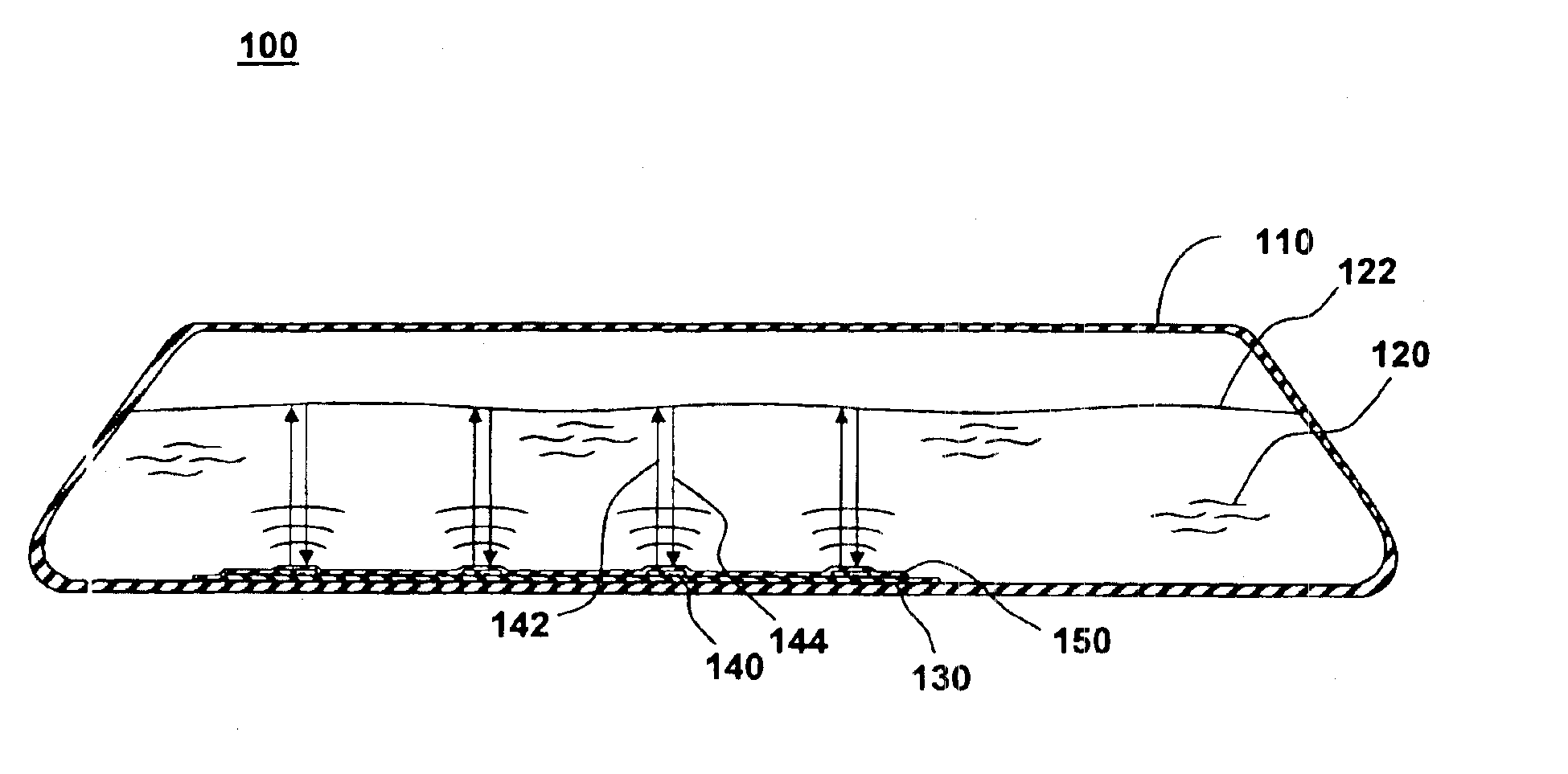
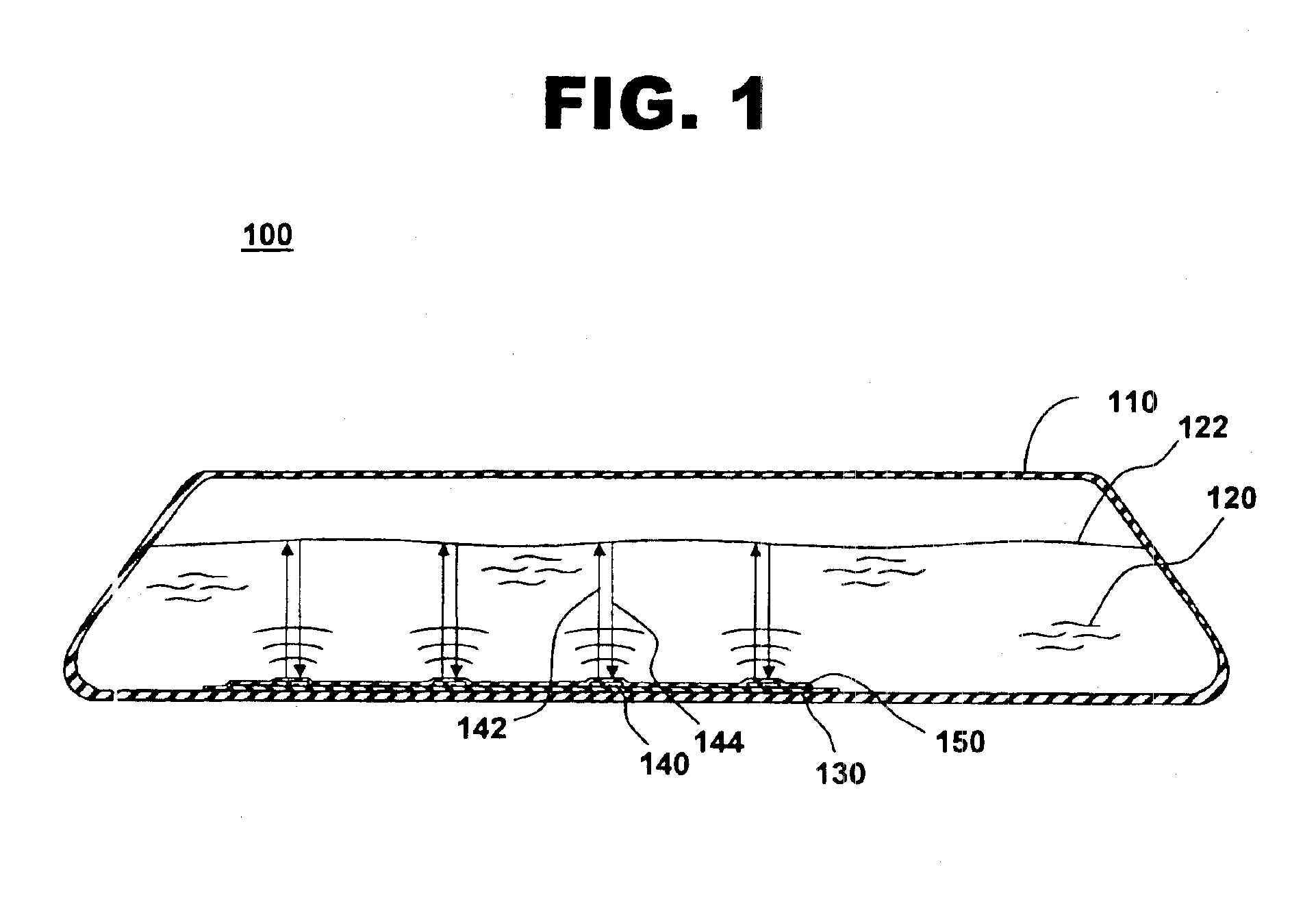
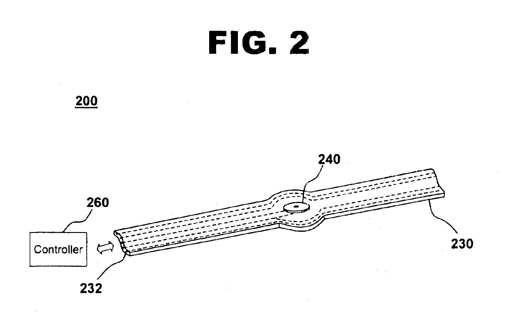
[0015]FIG. 1 illustrates an instrumented fuel-tank system, in accordance with one embodiment of the present invention at 100. Fuel-tank system 100 comprises a fuel tank 110 containing fuel 120, a transducer carrier tape 130 with one or more ultrasonic transducers 140, and a separation barrier 150.

[0016]Fuel tank 110 is a containment vessel for fuel 120, which may include, for example, gasoline, fuel oil, or jet fuel. In one embodiment for use in jet aircraft, fuel tank 110 may, for example, hold 50 gallons of fuel or less for use in smaller, propeller-driven general aviation craft, or in excess of 10,000 gallons for larger commercial and military aircraft. Fuel tank 110 may be located in a wing, a fuselage, or any suitable location within the aircraft. Fuel tank 110 may be filled or partially filled with fuel. A partially filled fuel tank 110 may have a fuel-air surface 122 at the interface between fuel 120 and air or other gaseous materials comprising the un-filled portion of fuel ...


PUM


Abstract

The invention provides a fuel-tank system with an ultrasonic fuel-gauging system for an aircraft. The fuel-tank system includes a fuel tank, a transducer carrier tape covered with a separation barrier, and coupled to a surface of the fuel tank, and at least one ultrasonic transducer attached to the transducer carrier tape. An ultrasonic signal from at least one ultrasonic transducer is reflected from a fuel-air surface and a reflected signal is received by at least one ultrasonic transducer to determine a fuel level in the fuel tank.

Description

FIELD OF THE INVENTION[0001]This invention relates generally to fluid level measurement systems and the integration of these systems. In particular, the invention relates more specifically to an ultrasonic fuel-tank gauging system for determining the amount of fuel in a fuel tank.BACKGROUND OF THE INVENTION[0002]Fuel monitoring systems for aircraft typically use capacitive fuel-gauging sensors. These sensors determine the amount of fuel in a tank by measuring the pressure near the bottom of the tank relative to a measurement of pressure above the fuel-air interface, and determining the height of the fluid from the pressure differential. From the height of the fluid and knowledge of the tank geometry, the amount of fuel in the tank may be ascertained. The capacitive fuel-gauging sensors determine the differential pressure by deflecting a diaphragm or other deformable element, and measuring the deflection with a capacitive pickoff mechanism. Such sensing mechanisms typically require e...

Claims


Application Information

Patent Timeline
IPC IPC(8): G01F23/296
CPCG01F23/2962G01N2291/02836
Inventor SENIBI, SIMON D.ANDERSON, DAVID M.BANKS, DAVID L.CHILDRESS, JAMES J.RASSAIAN, MOSTAFA
Owner THE BOEING CO
Why Eureka
Try Eureka