
Embroidery machine

Inactive Publication Date: 2005-08-09
SUSR PRECISION CO LTD
View PDF3 Cites 16 Cited by
  • Summary
  • Abstract
  • Description
  • Claims
  • Application Information

AI Technical Summary

Benefits of technology

[0013]Another object of the present invention is to provide an embroidery machine, which allows a worker to conveniently embroider a sewing object.
[0014]A further object of the present invention is to provide an embroidery machine, which has a structure suitable for production of various kinds and small amounts of goods, can facilitate the production of goods, and thereby can reduce the manufacturing cost.

Problems solved by technology

However, it is impossible for only one conventional embroidery machine to simultaneously embroider more than one kind of sewing objects (e.g., including at least two of a flat sewing object, a tubular sewing object, and a cap-shaped sewing object).
Thus, one embroidery machine cannot simultaneously embroider multiple kinds of sewing objects including flat objects, tubular objects, and sewing objects for caps.
However, the independent-type driving embroidery machine as described above includes a shuttle bed having a short length suitable to embroider flat objects and has a difficulty in embroidering a tubular object such as a cap or a T-shirt.

Method used


Image

  • Embroidery machine
  • Embroidery machine
  • Embroidery machine

Examples


Embodiment Construction

[0024]Hereinafter, a preferred embodiment of the present invention will be described with reference to the accompanying drawings. In the following description and drawings, the same reference numerals are used to designate the same or similar components, and so repetition of the description on the same or similar components will be omitted.

[0025]An embodiment of the present invention will be now explained referring to the FIGS. 1 through 4.

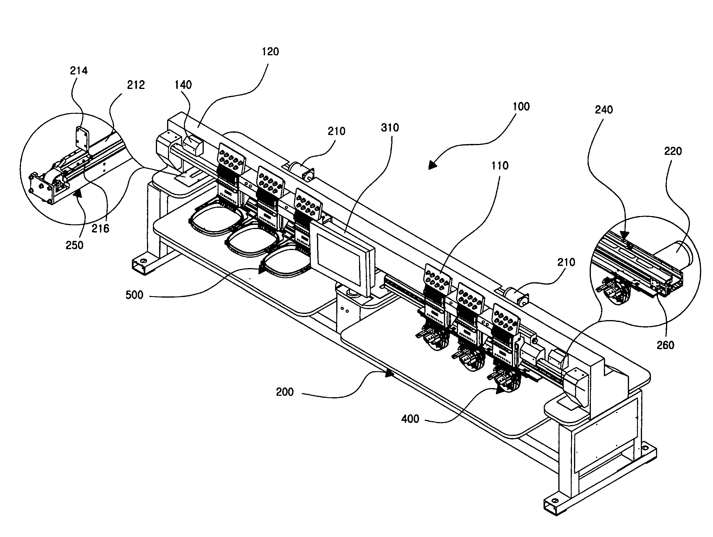
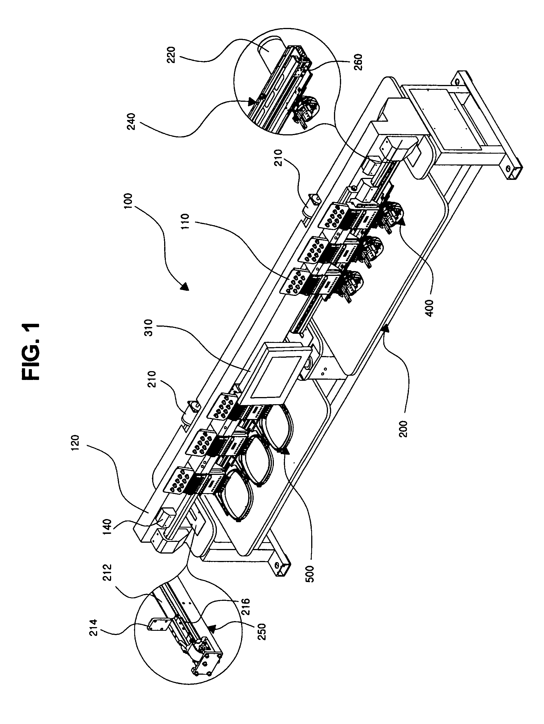
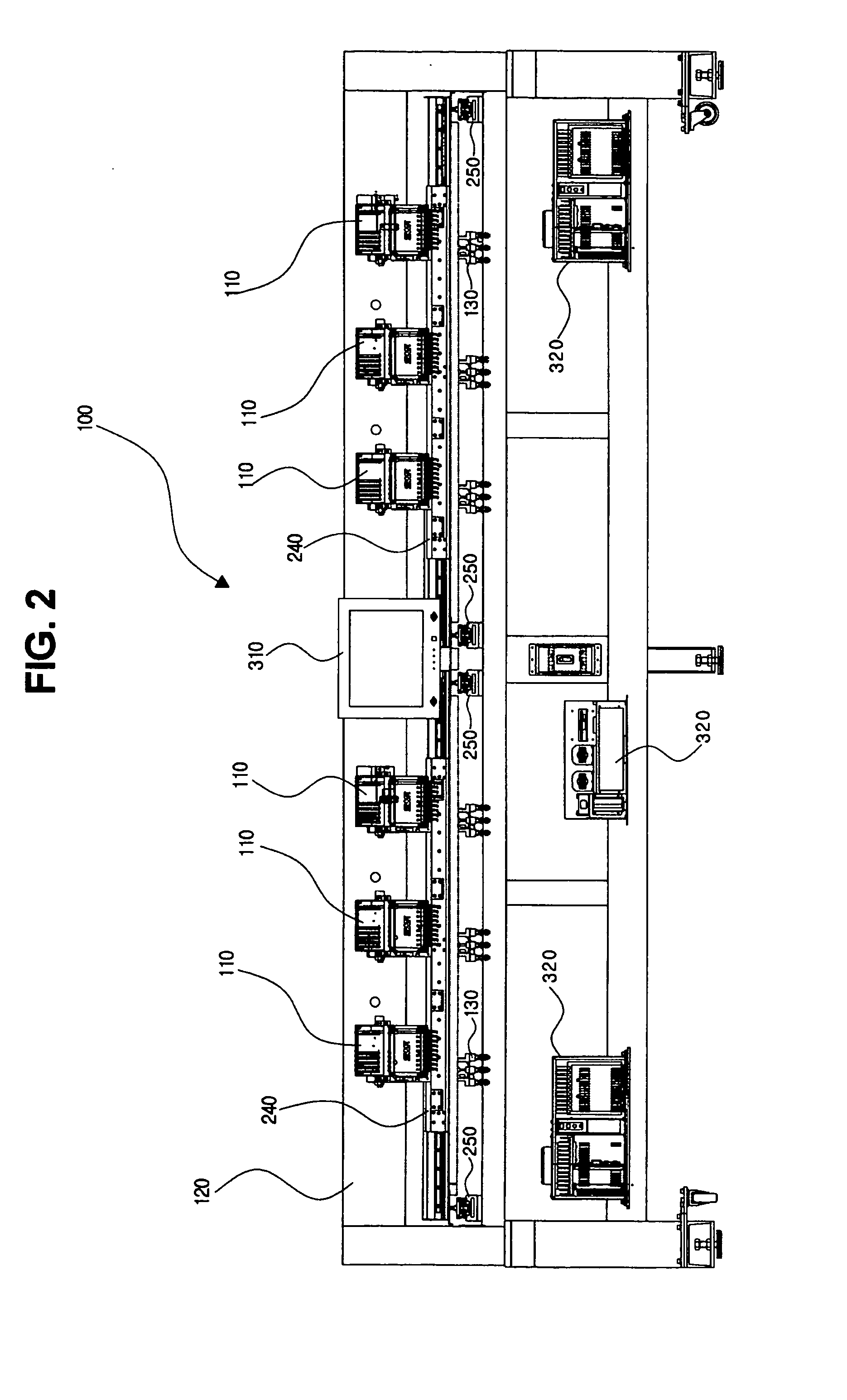
[0026]FIG. 1 is a perspective view for showing an embroidery machine according to an embodiment of the present invention. FIG. 2 is a front view of the embroidery machine shown in FIG. 1. FIG. 3 is a plan view of the embroidery machine shown in FIG. 1. FIG. 4 is a side view of the embroidery machine shown in FIG. 1.

[0027]As shown in FIGS. 1 through 4, at least two working groups, each of which includes a plurality of sewing heads 110, are installed on a front side of an upper beam 120 while being spaced a predetermined distance apart from each oth...


PUM


Abstract

An embroidery machine can simultaneously embroider sewing objects having various shapes, including a flat object, an object having a shape of a usual processed cloth, an object having a shape of a cap, etc. The embroidery machine comprises a plurality of sewing heads grouped into at least two working groups, and the embroidering frames, each of which is arranged for one of the working groups. The embroidering frames have structures either identical to each other or different from each other. Therefore, one conventional embroidery machine can simultaneously embroider more than one kind of sewing objects, including at least two of a flat sewing object, a tubular sewing object, and a cap-shaped sewing object.

Description

BACKGROUND OF THE INVENTION[0001]1. Field of the Invention[0002]The present invention relates to an embroidery machine, and more particularly to a multi-functional embroidery machine, which can simultaneously embroider sewing objects having various shapes, including a flat object, an object having a shape of a usual processed cloth, an object having a shape of a cap, etc., without replacement or addition of the machine or any separate part for the machine.[0003]2. Description of the Prior Art[0004]As generally known in the art, embroidery machines can be classified into flat type embroidery machines and tubular type embroidery machines. In the flat type embroidery machine, a flat object is secured on a rectangular frame and is then embroidered by the cooperation between a sewing head and a reel unit. In the tubular type embroidery machine, an object having a shape of a usual processed cloth, such as T-shirt, or a sewing object shaped like a cap is secured and embroidered by a proces...

Claims


Application Information

Patent Timeline
IPC IPC(8): D05C9/00D05C9/02D05C3/00D05C3/02D05B25/00D05C7/00
CPCD05C3/02D05C9/02D05C9/04
Inventor KANG, DOO-HWA
Owner SUSR PRECISION CO LTD
Learn More