

Air-cooled four-stroke internal combustion engine
- Summary
- Abstract
- Description
- Claims
- Application Information
AI Technical Summary
Benefits of technology
Problems solved by technology
Method used
Image

Examples
first embodiment
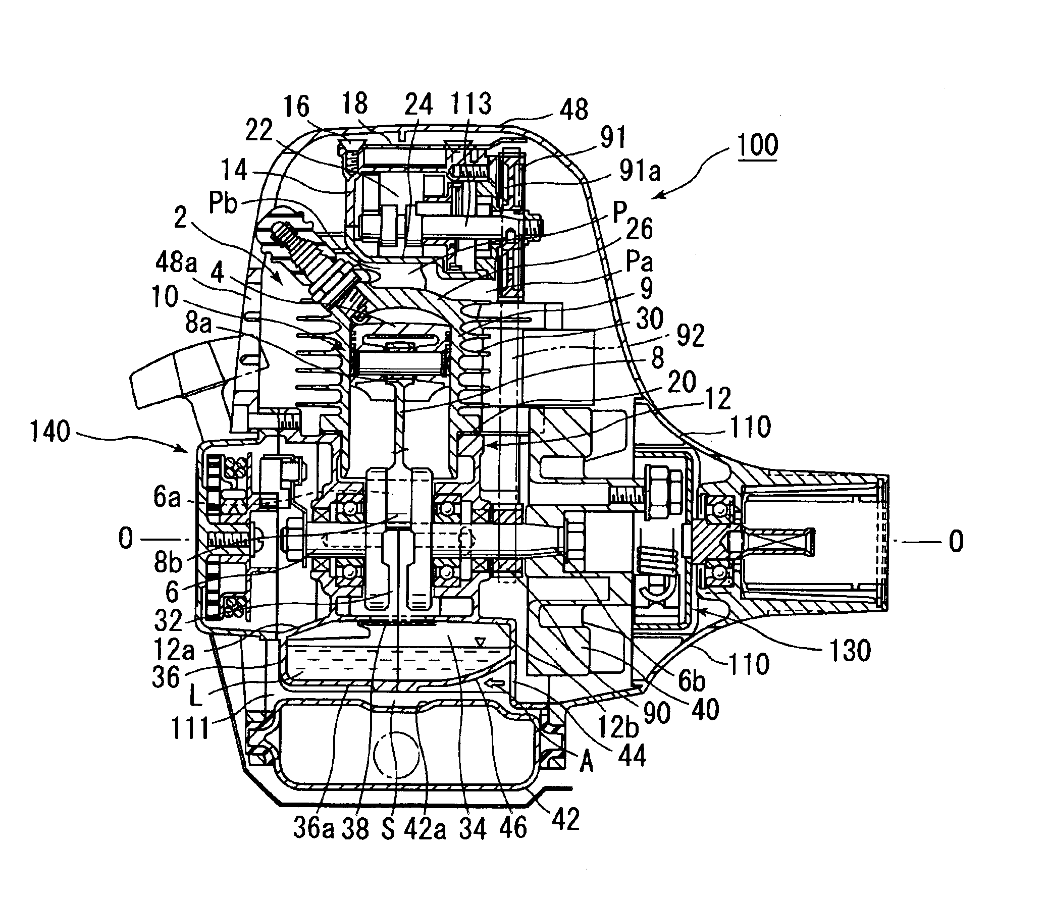
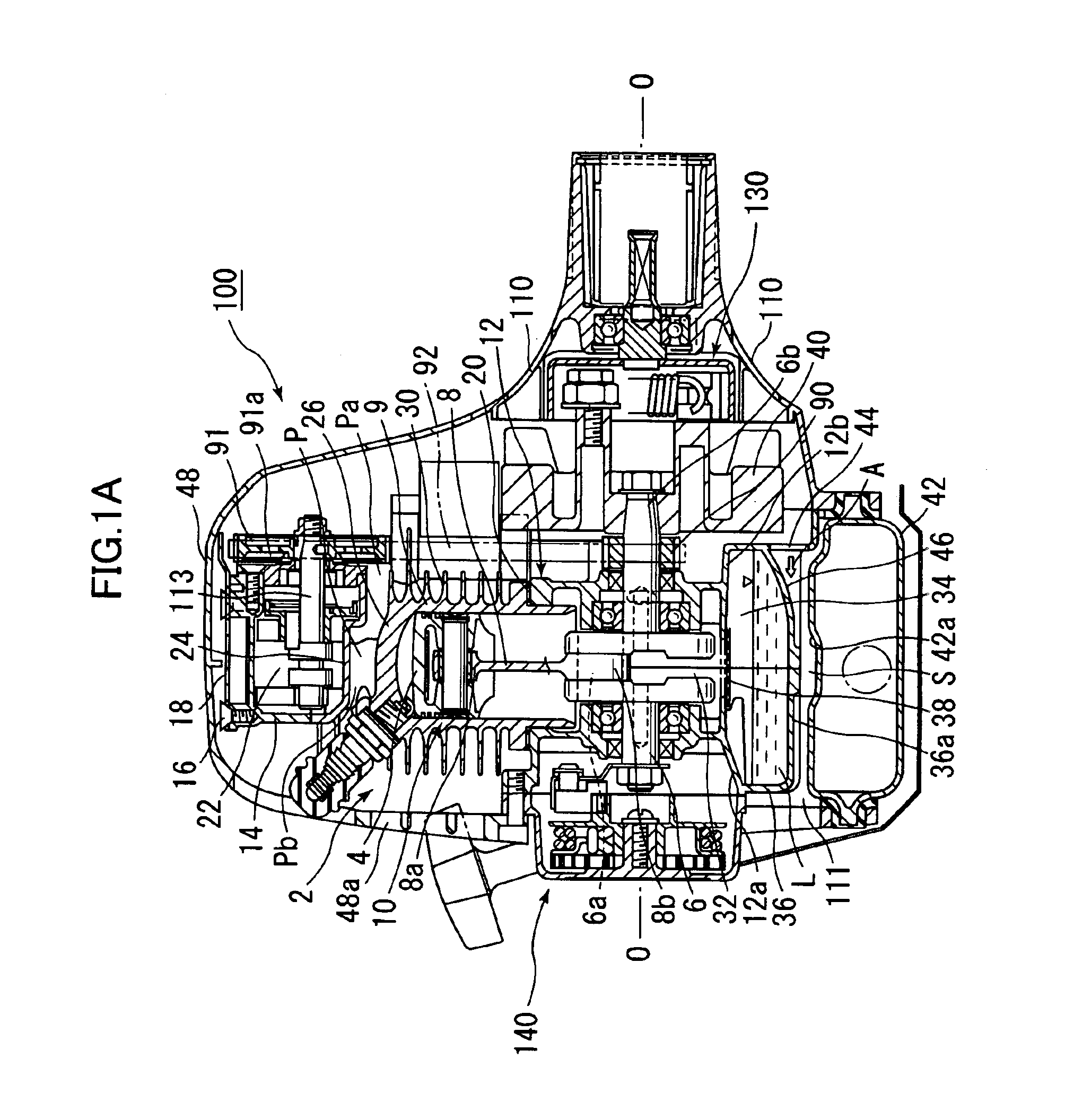
[0025]FIG. 1A shows a power output section 100 provided on the rear end of a portable trimmer having an air-cooled four-stroke engine according to the present invention. While the portable trimmer is omitted in FIG. 1A, it has a conventional structure comprising an output shaft which is contained in an operation rod linearly extending frontward from the power output section 100 and adapted to be driven by the drive section 100 through a centrifugal clutch 130, and a rotary blade adapted to be rotatably driven by the output shaft.
[0026]As shown in FIG. 1A, the air-cooled four-stroke engine 2 according to the first embodiment comprises a piston 4 adapted to be reciprocatingly moved in the vertical direction of the engine, a crankshaft 6 adapted to be rotatably driven in conjunction with the vertical reciprocating motion of the piston 4, and a connecting rod 8 which has an upper small end 8a connected to the piston 4 and a lower large end 8b connected to a crankpin 6a of the crankshaft...
second embodiment
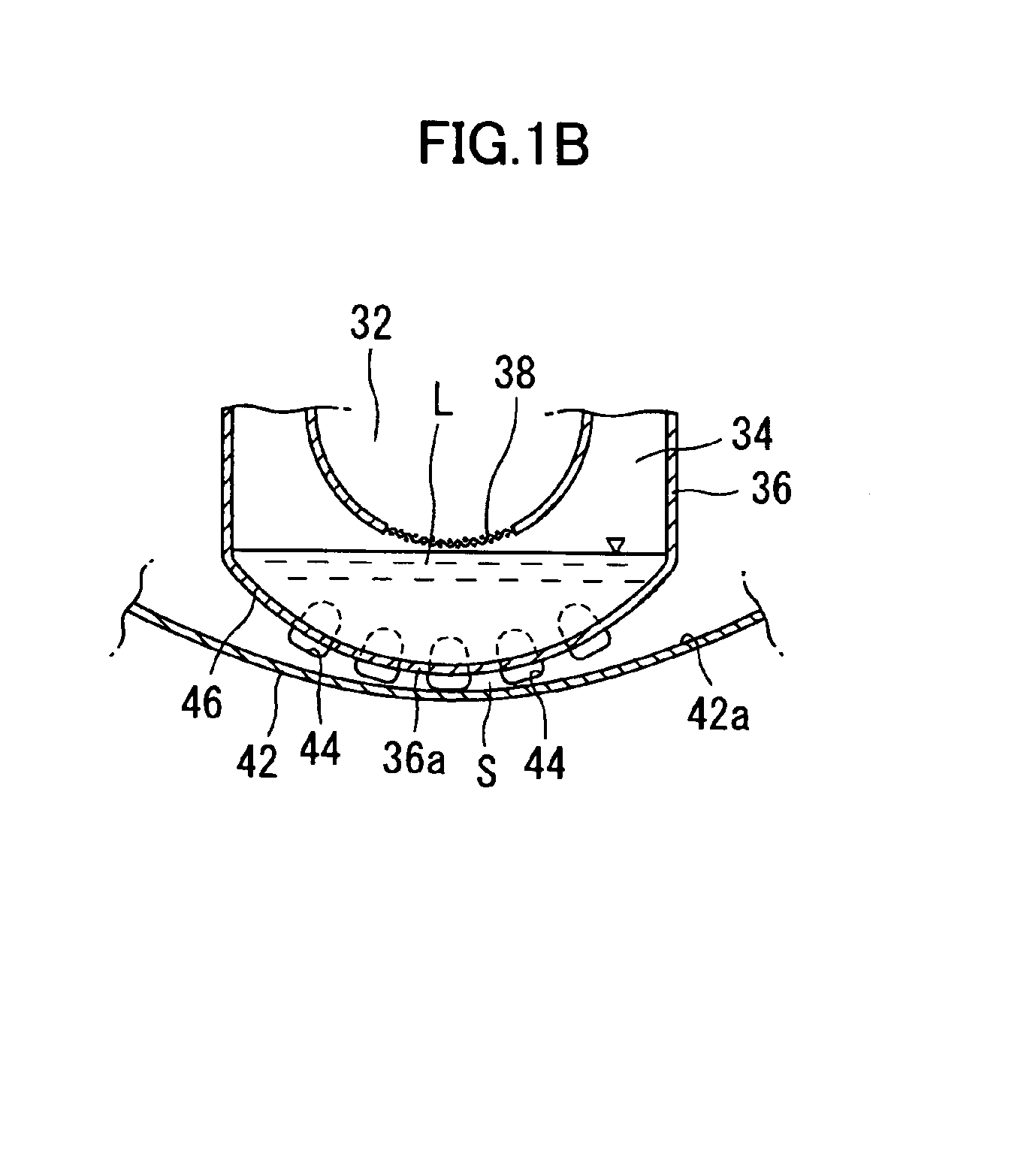
[0039]When the air-cooled four-stroke engine 50 is turned over (started) by operating a recoil starter 140, the crankshaft 6 rotates, and the fan rotor 40 is rotationally driven by the crankshaft 6 to suck the cooling air A from the upstream opening 112 toward the fan rotor 40. The cooling air A flows through the space S formed below the oil pan 36 to forcibly cool the lubrication oil L in the oil pan 36 located above the space S and fuel in a fuel tank 42 located below the space S. The cooling air A also flows through the channels 54 to provide an enhanced effect of cooling the lubrication oil in the oil pan 36.
[0040]The air-cooled four-stroke engine 60 according to a third embodiment of the present invention has the same structure as that of the air-cooled four-stroke engine 50 according to the second embodiment except for the shape of the lower surface 36a of an oil pan 36 and the flow direction of a cooling air A generated by a fan rotor 40. In FIGS. 3A and 3B, the same compone...
fourth embodiment
[0045]When the air-cooled four-stroke engine 70 is turned over (started) by operating a recoil starter 140, the crankshaft 6 is rotates, and a fan rotor 40 is rotationally driven by the crankshaft 6 to send cooling air from the fan rotor 40 toward the air-coaled four-stroke engine 70. A part A of the cooling air flows through a space S formed below the oil pan 36 to forcibly cool the lubrication oil L in the oil pan 36 located above the space S and fuel in a fuel tank 42 located below the space S. The cooling air A also flows between the fins to provide an enhanced effect of cooling the lubrication oil L in the oil pan 36.
[0046]As compared to the first embodiment having the space S formed below the oil pan 36 to allow the cooling air A to pass therethrough, the air-cooled four-stroke engine 80 according to a fifth embodiment includes a pipe 84 extending in the direction of the axis O-O of the crankshaft 6 to penetrate through lubrication oil L contained in a oil pan 36, instead of ...
PUM
 Abstract
Description
Claims
Application Information