Vibration damping clip

a technology of vibration damping and clip, which is applied in the direction of rod connections, machine supports, other domestic objects, etc., can solve the problems of lining to roll away from the edges to the slot, and the rubber lining can become dislodged from the mounting structure, so as to reduce the transmission of noise and vibration, easy to manufacture cost effectively, and rigid mounting structure

Inactive Publication Date: 2005-08-09
ILLINOIS TOOL WORKS INC
View PDF31 Cites 59 Cited by
  • Summary
  • Abstract
  • Description
  • Claims
  • Application Information

AI Technical Summary

Benefits of technology

[0011]An advantage of the present invention is providing a vibration damping clip that is easy to manufacture cost effectively, and which includes an energy absorbing layer to reduce the transmission of noise and vibration through the clip.
[0012]Another advantage of the present invention is providing a vibration damping clip having a mounting structure of relatively rigid material and a lining of relatively soft material in which the lining is physically locked to the mounting structure.
[0013]Still another advantage of the present invention is providing a vibration damping clip having a relatively rigid mounting structure and a relatively soft lining therefor in which the lining is not easily dislodged at end edges thereof or at the access opening to the clip.
[0014]Other features and advantages of the invention will become apparent to those skilled in the art upon review of the following detailed description, claims and drawings in which like numerals are used to designate like features.

Problems solved by technology

A problem has been experienced with some clips of this type in that the rubber lining can become dislodged from the mounting structure.
The force from the item and friction against the lining can cause the lining to roll away from the edges to the slot.

Method used


Image

  • Vibration damping clip
  • Vibration damping clip
  • Vibration damping clip

Examples


Embodiment Construction

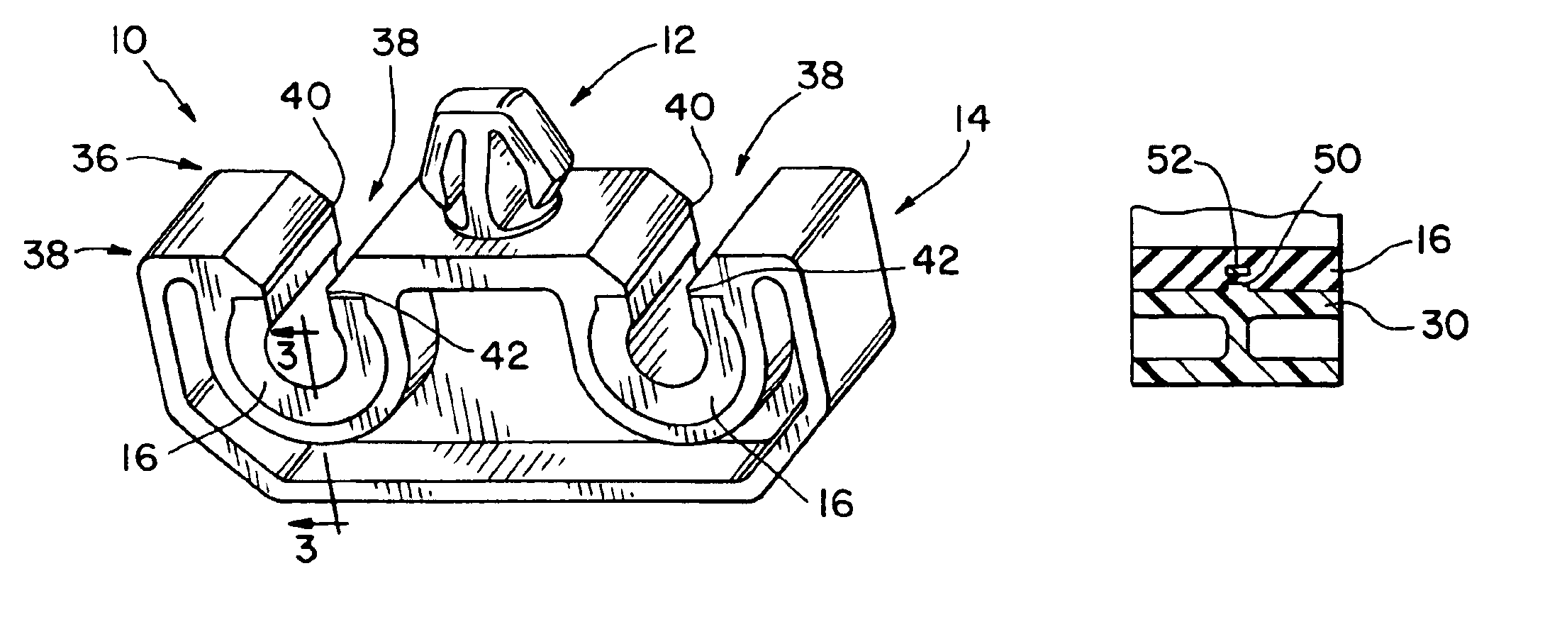
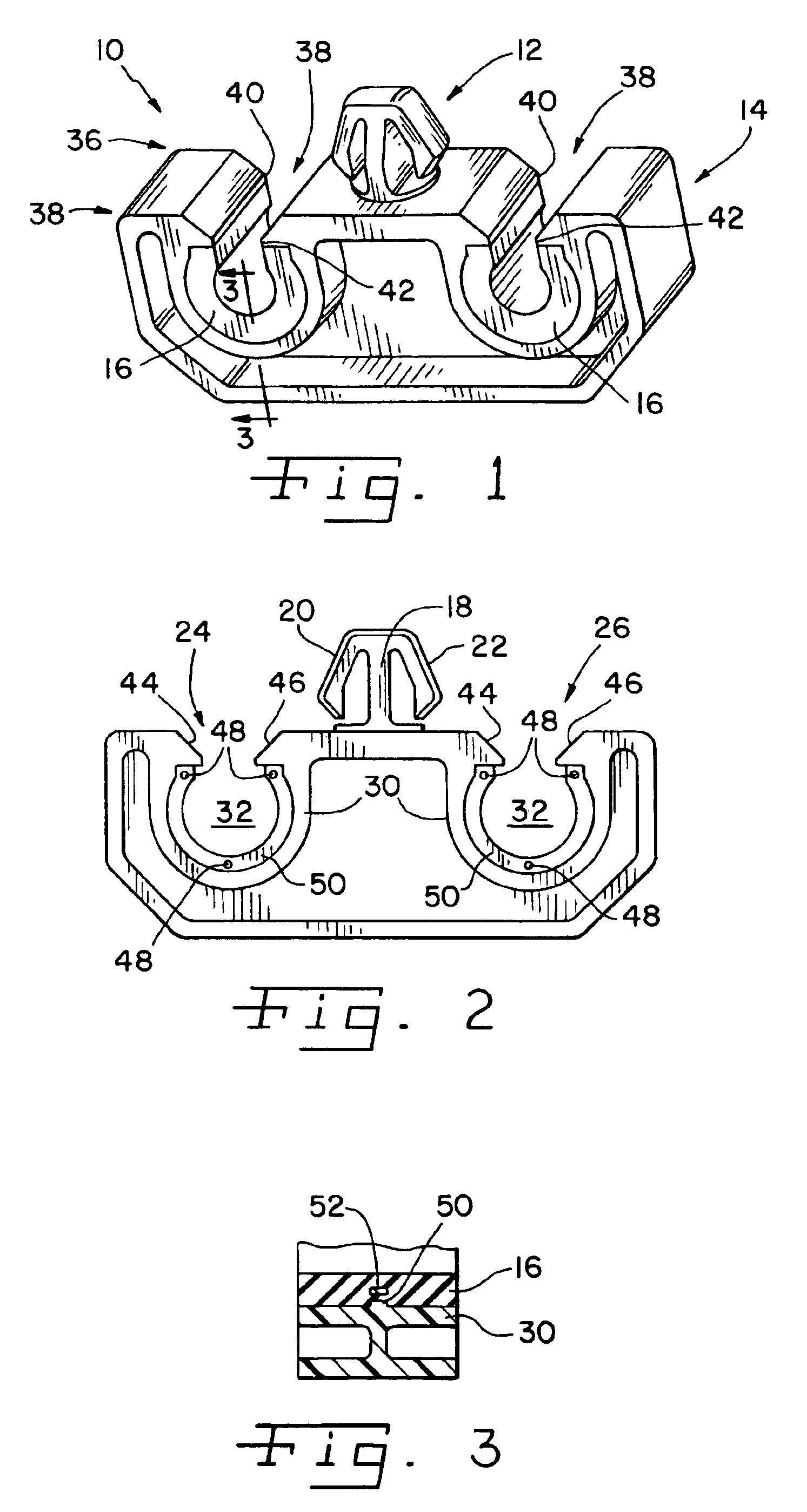
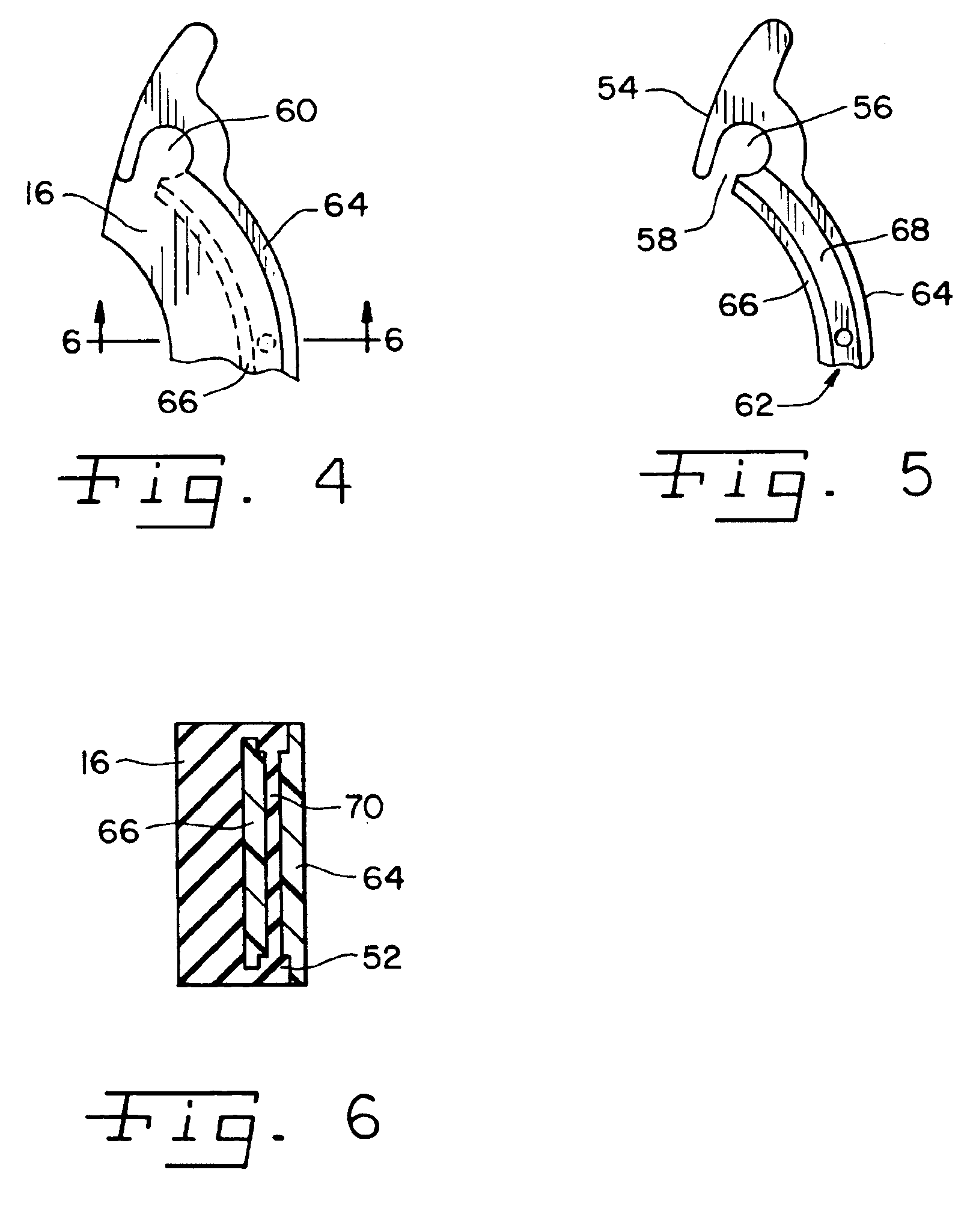
[0022]Referring now more specifically to the drawings and to FIG. 1 in particular, numeral 10 designates a holding device in the nature of a vibration damping clip in accordance with the present invention. Clip 10 includes a monolithic body of relatively rigid plastic material, such as nylon, forming an anchor part 12 and a holding part 14, and a holding part liner 16 of relatively softer material attached to holding part 14.

[0023]It should be understood that vibration damping clip 10 of the present invention can be configured for holding a variety of items such as, but not limited to break lines, tubes, wires and the like. Further, vibration damping clip 10 of the present invention can be configured for attachment to a variety of different articles, such as, but again not limited to automobiles, or different areas on the articles, such as the frame, body or other parts of an automobile. In that regard, the particular configurations of anchor part 12 and holding part 14 shown and to...


PUM


Abstract

A vibration damping clip of rigid material in which a softer lining is formed on the holding part of the clip including through an aperture in the holding part so that the lining is physically locked thereto. A similar lock is provided at an entrance or lead-in to the substantially annular holding portion of the clip.

Description

FIELD OF THE INVENTION[0001]The present invention relates to holding structures used for routing items such as pipes, tubes, wires and the like, and, more particularly, the invention relates to holding structures configured for reducing vibrations transferred between the holding structure and the article to which it is attached.BACKGROUND OF THE INVENTION[0002]Numerous types of holding devices are known for routing items such as tubes, pipes, wires, rods and the like. The holding device commonly includes some type of anchoring fixture for securing the holding device to the article on which it is used. The anchoring fixture can be a threaded part, a compressible clip for inserting into a hole, a mounting plate with holes for bolts, screws, rivets or the like, or any of a variety of other constructions that can be used to attach the holding device to the article, such as, for example, an automobile. The holding device will further include a holding part that holds the pipe, tube, rod,...

Claims


Application Information

Patent Timeline
Patent Type & Authority Patents(United States)
IPC IPC(8): F16B5/06F16B7/04
CPCF16B5/0685F16B7/0433F16L3/237F16L55/035B29L2031/7282
Inventor SHEREYK, DAVID A.BENOIT, THOMAS A.
Owner ILLINOIS TOOL WORKS INC
Why Eureka
Try Eureka