Supporting mechanism for solid type rod integrator

a technology of integrator and support mechanism, which is applied in the field of projectors, can solve the problems of easy generation of scratching or chipping, dispersion of light or light, and provide total reflection, so as to reduce the amount of scratching and chipping, and reduce the amount of first side surface soiling

Inactive Publication Date: 2005-08-09
SEIKO EPSON CORP
View PDF7 Cites 13 Cited by
  • Summary
  • Abstract
  • Description
  • Claims
  • Application Information

AI Technical Summary

Benefits of technology

[0021]In another embodiment, the fist holding unit preferably covers the first side surface except areas having predetermined widths from edges of the first side surface. With this embodiment, soiling of the first side surface can be reduced because it is covered by the holder.
[0022]When the first side surface is divided in a direction of a light axis of the rod integrator into: an entrance part which is adjacent to a light entrance plane of the rod integrator; a projection part which is adjacent to a light projection plane of the rod integrator, and a middle part disposed between the entrance part and the projection part, the following embodiment is preferred. In this embodiment, the first contact portion contacts only the middle part. Scratching and chipping of the rod integrator is easily generated in the vicinity of the edge between the side surface and the light entrance plane or the light projection plane by a holder. In an above arrangement, the edges are not contacted by the holder. Accordingly, such scratching and chipping can be reduced or eliminated.

Problems solved by technology

When the surface is soiled, it can not provide total reflection, which is provided when the surface is not soiled.
This results in the dispersion of the light or the generation of the light, which does not meet the condition of total reflection.
The scratching or chipping is easily generated especially in the vicinity of the edge of the rod integrator.

Method used


Image

  • Supporting mechanism for solid type rod integrator
  • Supporting mechanism for solid type rod integrator
  • Supporting mechanism for solid type rod integrator

Examples


Embodiment Construction

[0034]Preferred exemplary embodiments of the invention are described below.

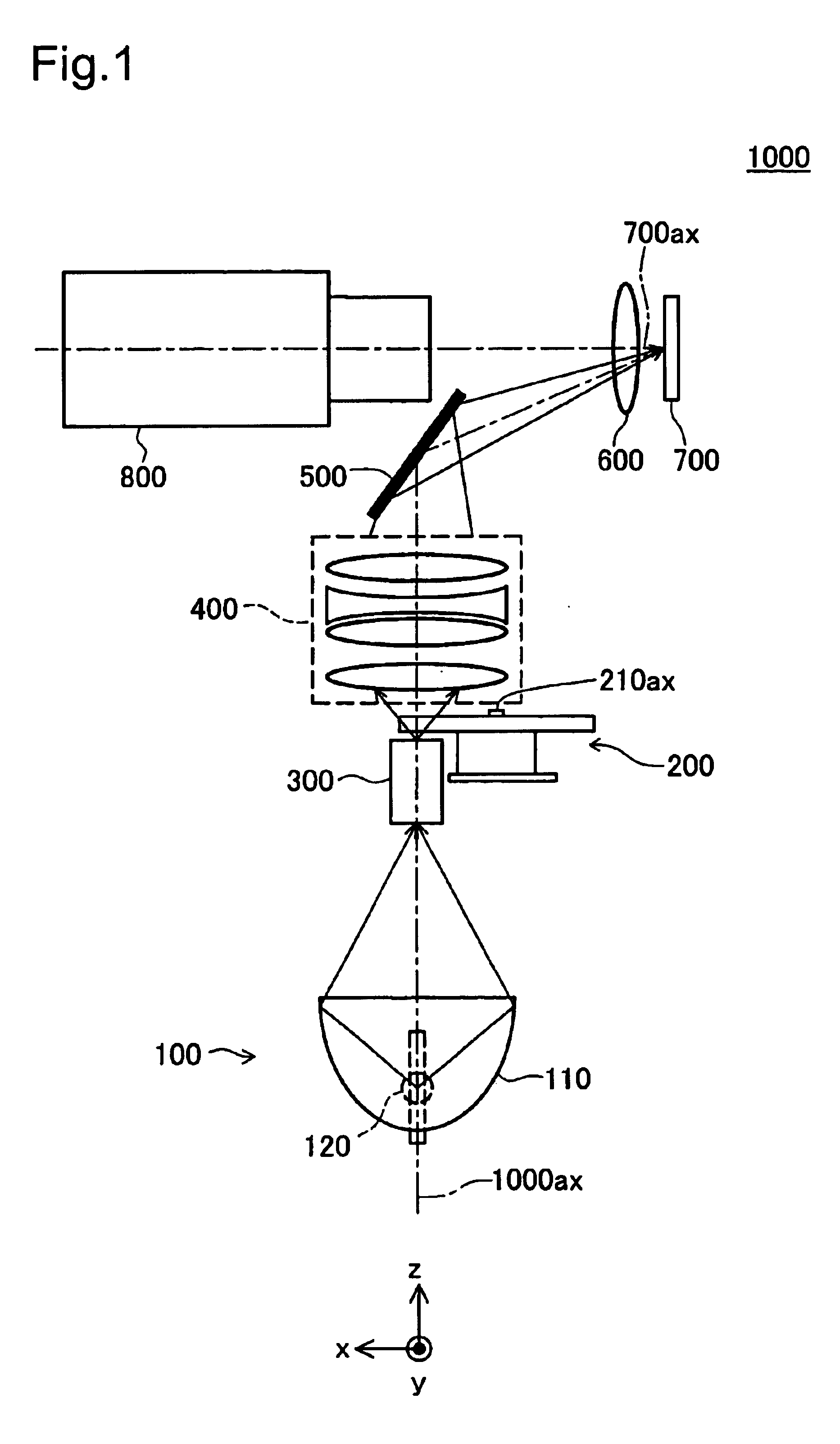
[0035]FIG. 1 shows the general structure of a projector to which is applied a supporting mechanism for a rod integrator according to one embodiment of this invention. Projector 1000 has a light source device 100, a color wheel 200, a solid type rod integrator 300 equipped with the supporting mechanism described below, a relay optical system 400, a reflection mirror 500, a field lens 600, a reflective optical modulation device 700, a projecting lens 800 disposed along the system optical axis 1000ax in the listed order. Hereinafter, the direction from the light source device 100 to the reflection mirror 500 along the system optical axis 1000ax is described as direction z, the direction perpendicular to the direction z in the paper plane of FIG. 1 is described as direction x, and the direction perpendicular to the direction z and the paper plane of FIG. 1 is described as direction y.

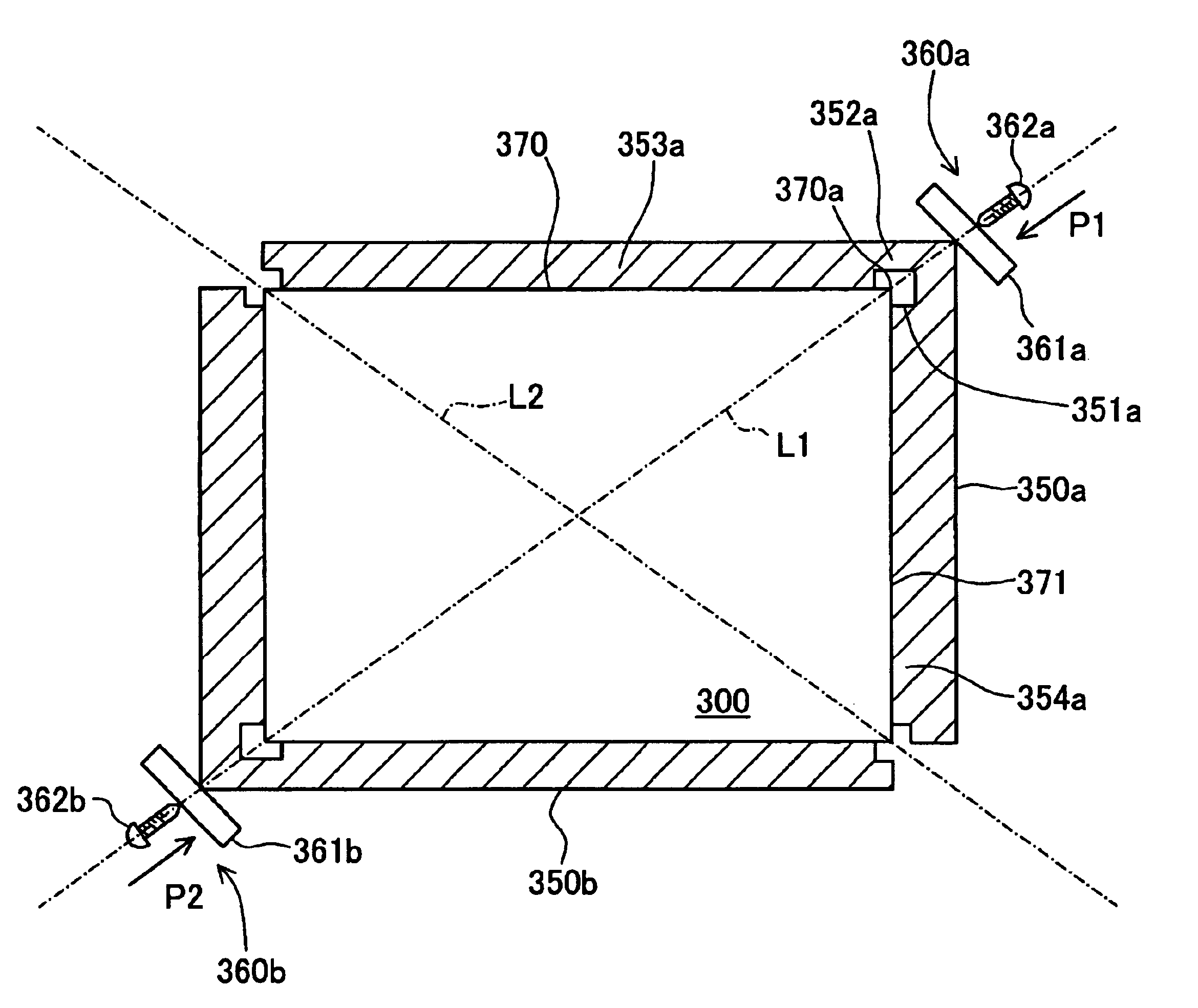
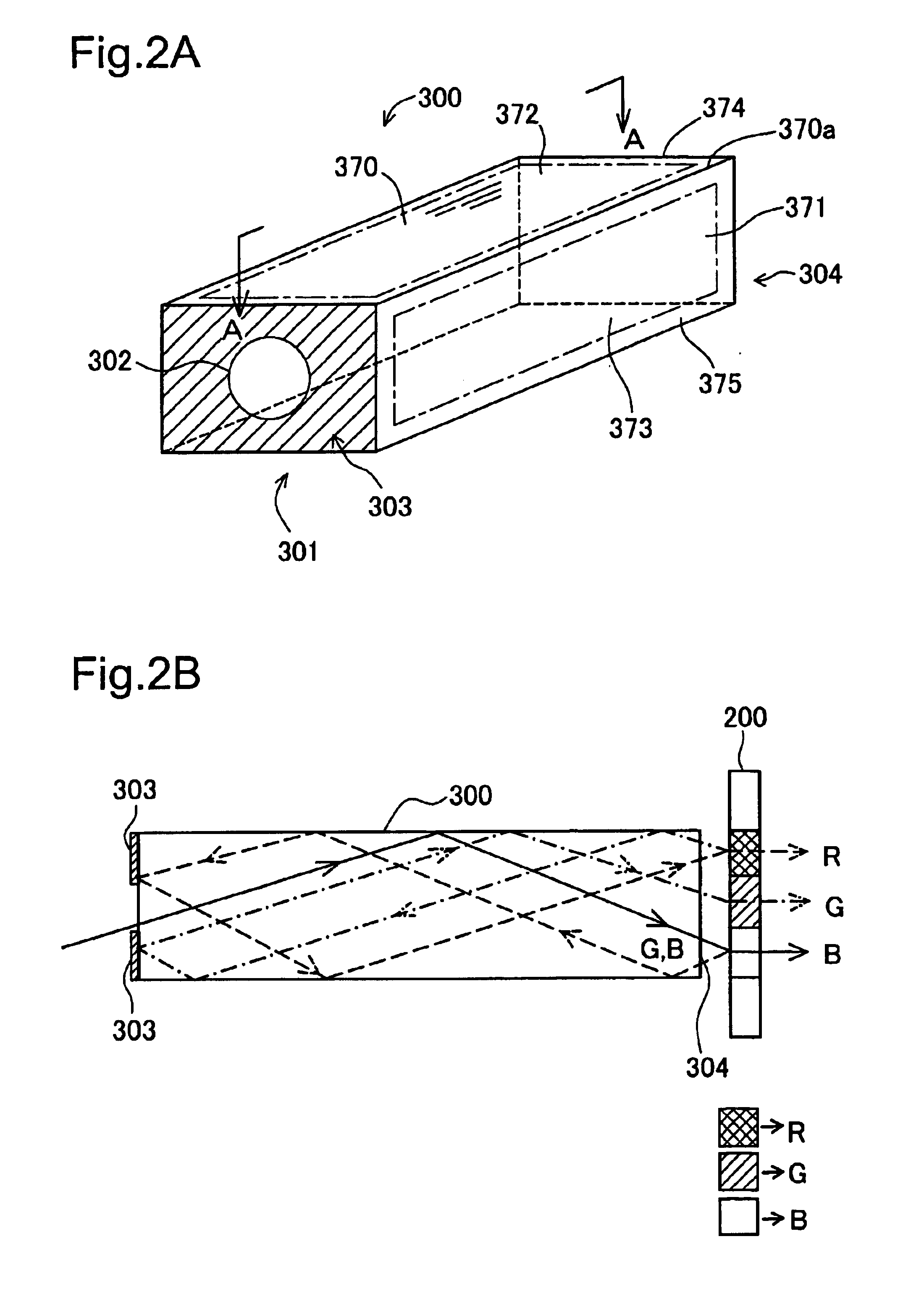
[0036]The rod integrator 300 ...


PUM


Abstract

The supporting structure for a rod integrator 300 includes, for example, holding members 350a, 350b for holding the rod integrator 300, and supporting units 360a, 360b for supporting the holding members. Each holding member 350a contacts by its planar portions (walls) respectively with two side surfaces of the rod integrator 300 adjacent to one another. The holding member 350a has a clearance such that the holding member does not contact with the edge shared by the two side surfaces of the rod integrator 300. The supporting unit 360a includes, for example, a supporting member 361a and screw 362a. The supporting unit 360a supports the rod integrator 300 by pressing of the screw 362a along the direction of the diagonal of the rod integrator 300 via the supporting member 361a. By doing so, chipping and scratching proximate to the edge can be reduced, and soiling of the reflecting plane can be prevented.

Description

FIELD OF THE INVENTION[0001]The present invention relates to a projector for projecting an image, and in particular to a supporting mechanism for a rod integrator used in an optical system of the projector.DESCRIPTION OF RELATED ART[0002]In the conventional projector, an optical modulation device, e.g., a liquid crystal panel or a DMD (Digital Micromirror Device: a trade mark of TexaxInstruments), is illuminated by light projected from a light source device. The optical modulation device modulates the projected light according to the image signals. The projector optical system displays an image on the screen by projecting the image light which emerged from the optical modulation device to the screen.[0003]In such a projector, the uniformity of the illuminance is improved by a rod integrator provided on the light path of the light optical system between the light source device and the optical modulation device. Different types of rod integrators, for example, a tunnel type and a soli...

Claims


Application Information

Patent Timeline
Patent Type & Authority Patents(United States)
IPC IPC(8): G02B6/00G02B6/32G03B21/00G03B21/14H04N5/74
CPCG03B21/00G03B21/14G03B21/208G03B21/005G03B21/145
Inventor AKIYAMA, KOICHI
Owner SEIKO EPSON CORP
Why Eureka
Try Eureka