Infrared temperature sensors for solar panel

a solar panel and infrared technology, applied in the direction of optical radiation measurement, fire alarms, instruments, etc., can solve the problems of high labor intensity and cost, the lead connecting the thermocouple to the system processor is susceptible to damage, and the replacement of broken or damaged thermocouples or thermocouple leads is also labor intensive and costly

Inactive Publication Date: 2005-08-09
UNITED TECH CORP +2
View PDF21 Cites 64 Cited by
  • Summary
  • Abstract
  • Description
  • Claims
  • Application Information

AI Technical Summary

Benefits of technology

[0008]In one preferred embodiment of the present invention, a solar receiver system is provided for utilizing solar energy to produce electrical power and to generate a temperature profile of a plurality of receiver tubes utilized in the system. The solar receiver system includes a solar receiver having a plurality of receiver panels. Each receiver panel includes the plurality of receiver tubes through which the coolant flows. Additionally, the solar receiver system includes a plurality of IR cameras adapted to view at least a portion of a surface area of the solar receiver. Each IR camera is located having a specified spatial relationship with the solar receiver and is adapted to have a field of view including a different specified region of the surface area of the solar receiver. Furthermore, the solar receiver system includes a master control system adapted to receive an IR color image from each IR camera, wherein each IR image depicts surface area temperatures and variances of the region of the solar receiver viewed by each IR camera. The master control system translates the IR images into digital temperature data comprising discrete temperature values at a plurality of points equally spaced along a length of each of the receiver tubes. Additionally, the master control system generates a temperature profile of the surface area

Problems solved by technology

This would be very labor intensive and costly.
Additionally, over time, due to the expansion and contraction of the receiver tubes, caused by the heating and cooling of each tube, the thermocouples and the leads connecting the thermocouples to the system processor would be susceptible to damage.
Replacing broken or damaged thermocouples or thermocouple leads would also be very labor intensive and costly.
Furthermore, having thermocouples sporadically placed throughout each receiver panel allows the potential for damage to the receiver tubes.
Thus,

Method used


Image

  • Infrared temperature sensors for solar panel
  • Infrared temperature sensors for solar panel
  • Infrared temperature sensors for solar panel

Examples


Embodiment Construction

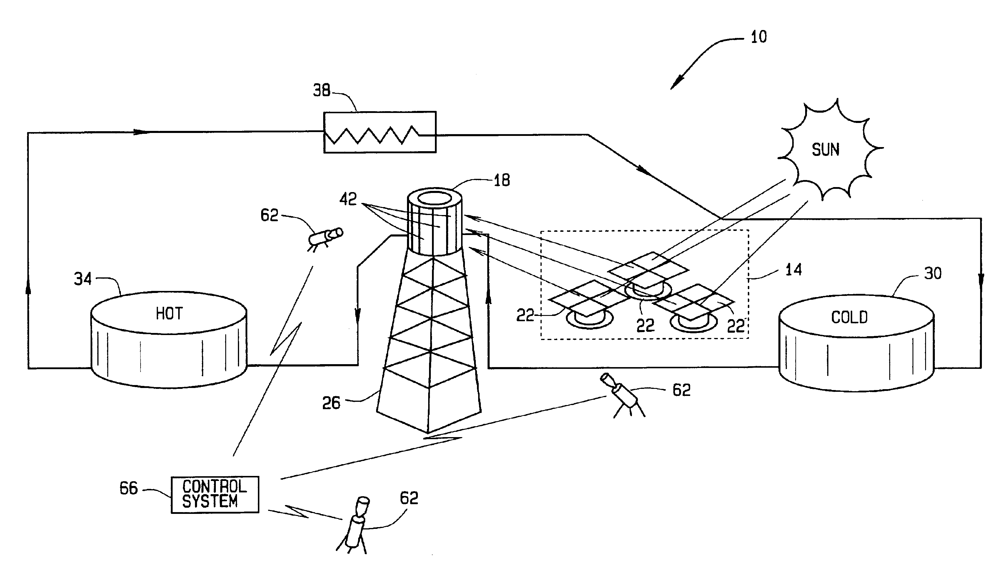
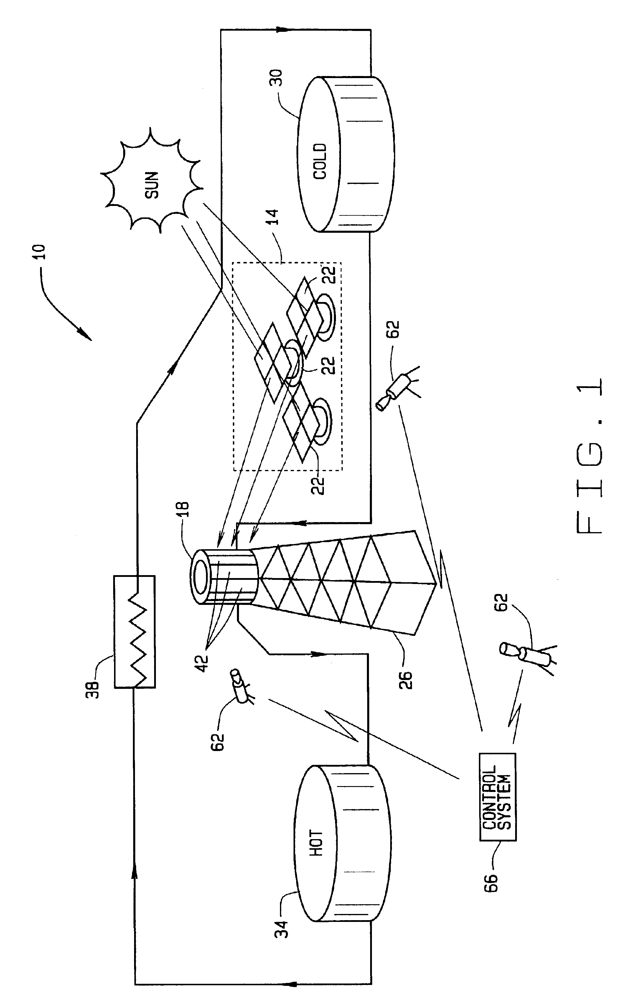
[0015]FIG. 1 is a simplified schematic representation of a solar receiver system 10 in accordance with a preferred embodiment of the present invention. Solar receiver system 10 includes a collector system 14 that intercepts the sun's thermal energy and redirects the thermal energy to a heat exchanger called a solar receiver 18. Collector system 14 includes a plurality of sun tracking mirrors called heliostats 22. Collector system 14 could include up to one thousand or more heliostats 22 depending on the overall size of system 10. Thermal, or solar, energy from the sun is redirected to the solar receiver 18 by heliostats 22. In a preferred embodiment, solar receiver 18 is mounted on a tall tower 26 typically 150 feet to 250 feet (45.7 meters to 76.2 meters) or more in height. Alternatively, solar receiver 18 can be mounted to a ground level platform or mounted below ground level in a recess. Coolant at about 550° F. is pumped out of a cold thermal storage tank 30 to the solar receive...


PUM


Abstract

A solar receiver system for utilizing solar energy to produce electrical power and to generate a temperature profile of a plurality of receiver tubes utilized in the system. The solar receiver system includes a solar receiver having a plurality of receiver panels including the plurality of receiver tubes through which a coolant flows. Additionally, the solar receiver system includes a plurality of IR cameras adapted to view at least a portion of a surface area of the solar receiver. Each IR camera is adapted to have a field of view including a different specified region of the surface area of the solar receiver. Furthermore, the solar receiver system includes a master control system adapted to receive an IR image from each IR camera, wherein each IR image depicts surface area temperatures and variances over the region of the solar receiver viewed by each IR camera. The master control system generates a temperature profile of the surface area of the solar receiver utilizing the IR images.

Description

FIELD OF INVENTION[0001]The invention relates generally to monitoring the temperature of a solar panel. More specifically, the invention relates to a system for obtaining a continuous temperature profile of a plurality of receiver tubes as a heat transfer fluid flows through the tubes. The receiver tubes are included in a plurality of solar panels that comprise a solar receiver power tower. The system utilizes a plurality of (IR) cameras to measure and record temperature values and variances over an entire surface area of the solar receiver, thereby yielding the continuous temperature profile of the outside surface of receiver tubes.BACKGROUND OF THE INVENTION[0002]A solar power tower is a power plant that converts solar thermal energy into electrical energy for connection to a utility grid. It can be sized to produce a wide range of power for commercial use from about 1 MWe to about 200 MWe.[0003]The sun's thermal energy is intercepted by a collector system that is comprised of tho...

Claims


Application Information

Patent Timeline
IPC IPC(8): G01J5/00
CPCF24J2/07F24J2/402F24J2/42F24J2/4621F24J2/4649G01J2005/0077Y02E10/41F24S80/20F24S50/40F24S90/00F24S40/50F24S20/20Y02E10/40
Inventor LITWIN, ROBERT ZACHARY
Owner UNITED TECH CORP
Why Eureka
Try Eureka