Electrical connector having improved terminals

a technology of electric connectors and terminals, applied in the direction of electrical equipment, coupling device connections, printed circuits, etc., can solve the problems of difficulty in achieving the accurate positioning of the soldering portion of the and the smt terminals with respect to the corresponding through-holes and pads of the pcb at the same tim

Inactive Publication Date: 2005-08-09
HON HAI PRECISION IND CO LTD
View PDF12 Cites 21 Cited by
  • Summary
  • Abstract
  • Description
  • Claims
  • Application Information

AI Technical Summary

Benefits of technology

[0007]Accordingly, it is an object of the present invention to provide an electrical connector, the terminals of which can be accurately soldered with a printed circuit board.

Problems solved by technology

However, a problem occurs, when THE terminals and SMT terminals are simultaneously required in one electrical connector in some applications, that it is difficult to achieve an accurately positioning between the soldering portions of THE and SMT terminals with respect to corresponding through-holes and pads of the PCB at the same time.

Method used


Image

  • Electrical connector having improved terminals
  • Electrical connector having improved terminals
  • Electrical connector having improved terminals

Examples


Embodiment Construction

[0020]Reference will now be made to the drawing figures to describe the present invention in detail.

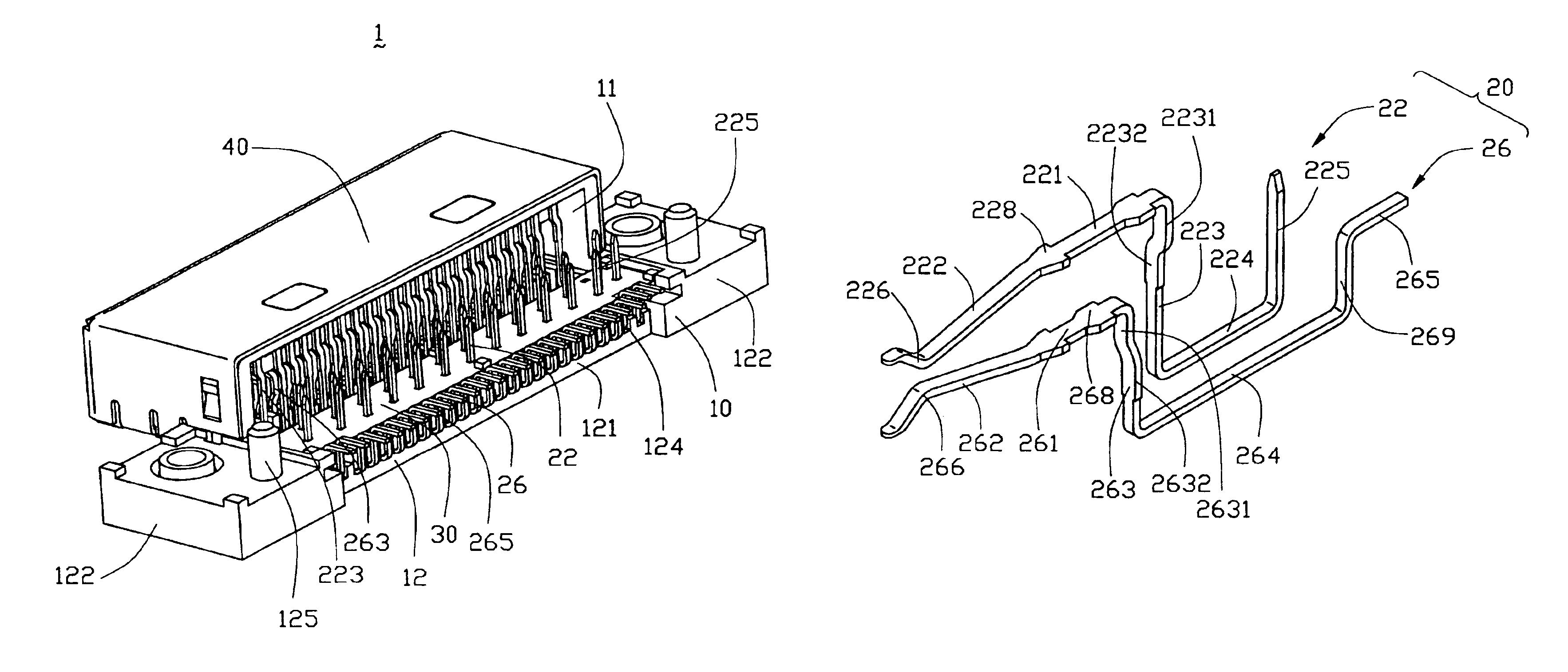
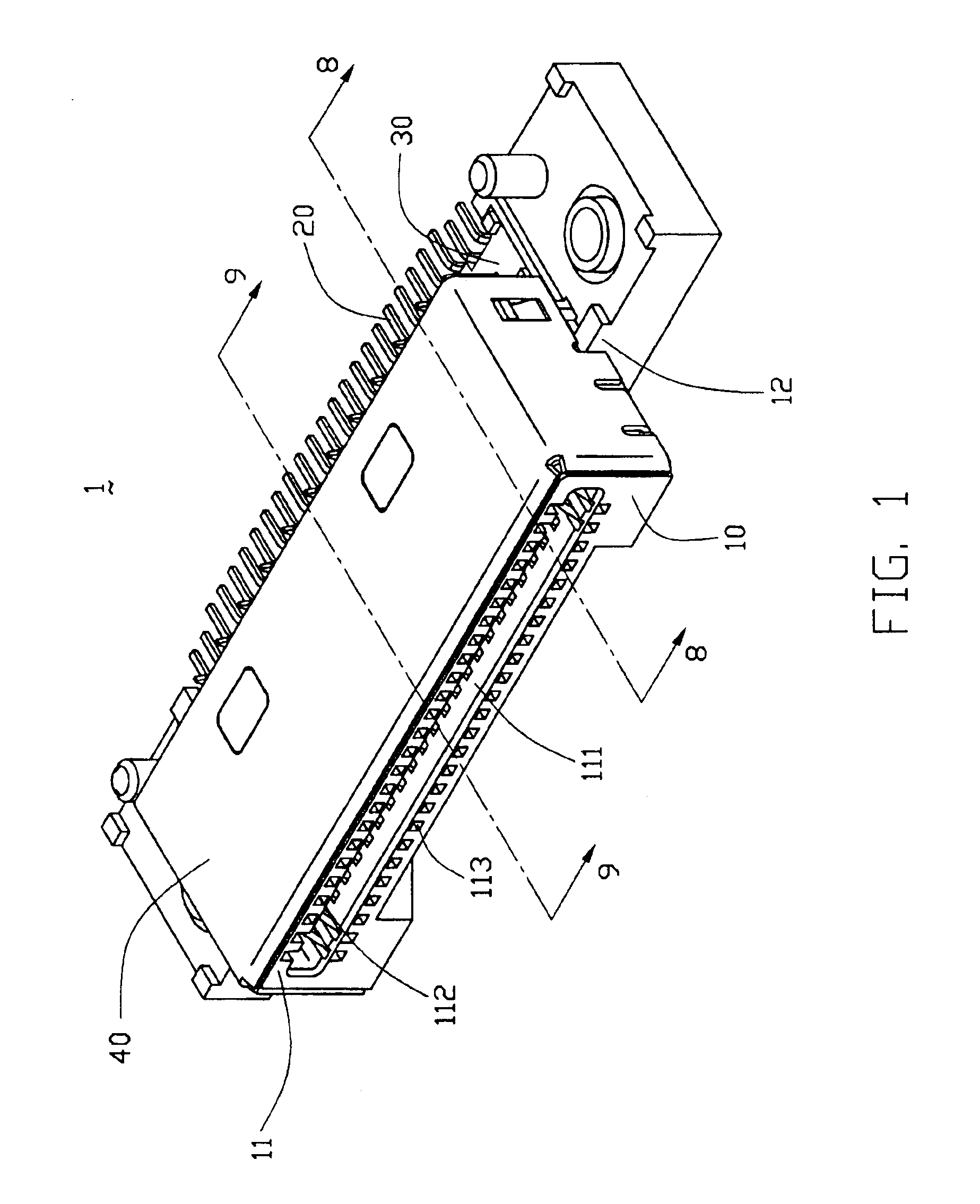
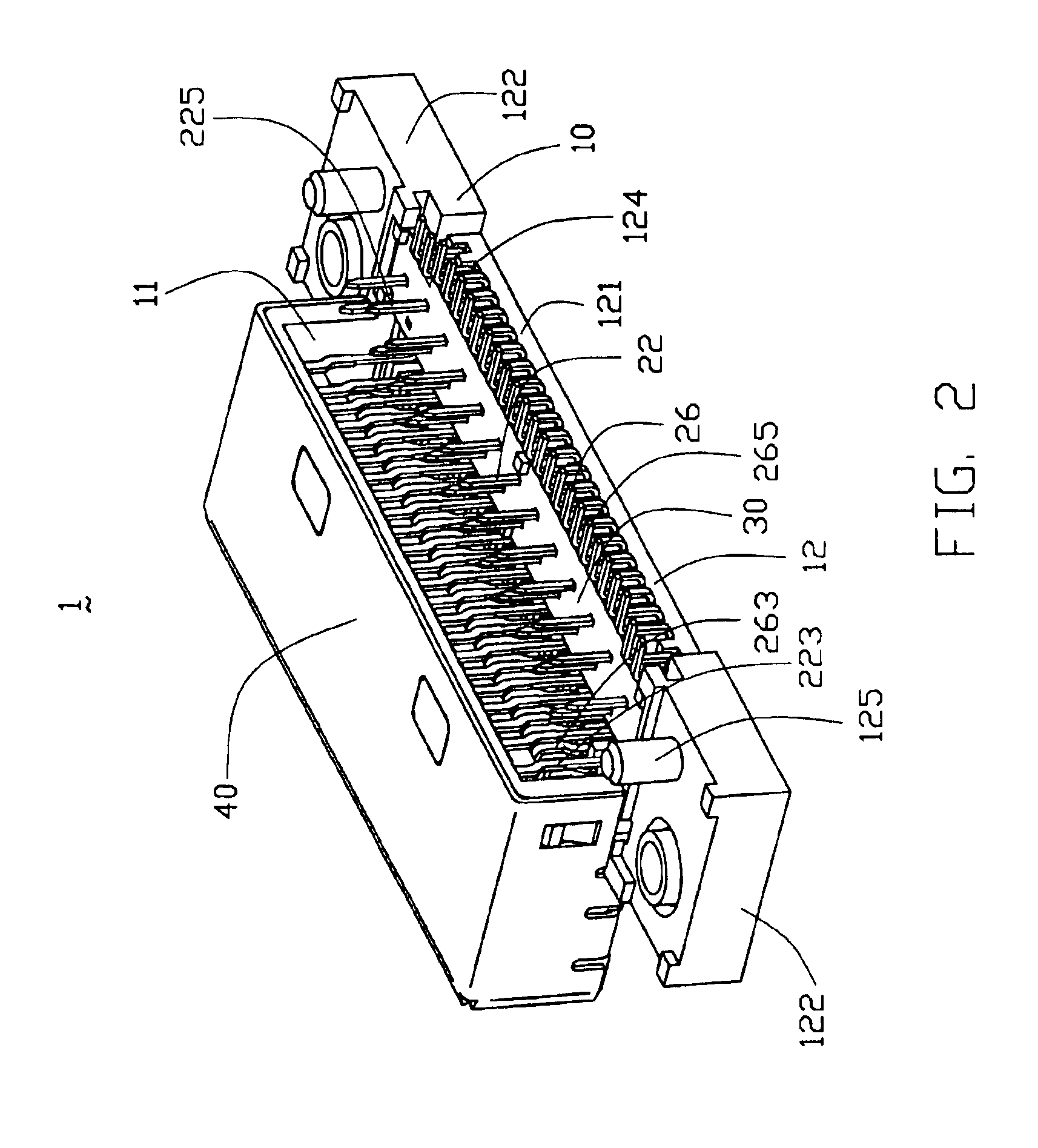
[0021]With reference to FIGS. 1-4, an electrical connector in accordance with the present invention, which is adapted for mounting on a printed circuit board (PCB) 50, comprises an insulative housing 10, a plurality of terminals 20 received in the insulative housing 10, a spacer 30 mounted on the insulative housing 10 and a shell 40.

[0022]The insulative housing 10 comprises a base portion 12 and a mating portion 11 extending forwardly from the base portion 12. The mating portion 11 comprises a mating port 111 and a plurality of first and second passageways 112, 113 extending through. The mating port 111 defines a receiving space 114 for mating with a complementary connector (not shown). The first passageways 112 and the second passageways 113 are arranged in upper and lower rows, respectively, for receiving the terminals 20. The base portion 12 comprises a pair of ladder portions 122 ...


PUM


Abstract

A board-mounted electrical connector (1) includes an insulative housing (10), a number of first terminals (22) and a number of second terminals (26) received in the housing, and a spacer (30) assembled on the housing. The insulative housing includes a base portion (12) defining a number of recesses (124) thereon. Each first terminal includes a contacting portion (222) and a soldering portion (225) extending perpendicularly to a printed circuit board (50). Each second terminal includes a contacting portion (262), a soldering portion (265) extending parallel to the PCB and a connecting portion (264) connecting the contacting portion and the soldering portion. The spacer defines a number of holes (33) for receiving and organizing the soldering portions of the first terminals and forms a number of protrusions (34) cooperating with the recesses of the base portion for organizing corresponding connecting portions of the second terminals to thereby precisely position the soldering portions of the second terminals.

Description

CROSS-REFERENCE TO RELATED APPLICATIONS[0001]Relevant subject matter is disclosed in a copending U.S. Patent Ser. No. application 10 / 879,675 titled “ELECTRICAL CONNECTOR HAVING A SPACER”, which is assigned to the same assignee with this application.BACKGROUND OF THE INVENTION[0002]1. Field of the Invention[0003]The present invention generally relates to an electrical connector, and particularly to an electrical connector mounted on a printed circuit board.[0004]2. Description of Related Arts[0005]It is well known that an electrical connector mounted on a printed circuit board (PCB) by either Through Hole Technology (THT) or Surface Mount Technology (SMT). U.S. Pat. No. 4,679,883 discloses a board-mounted electrical connector comprising an insulative housing and a plurality of terminals received in the insulative housing which are electrically connected to the PCB through THT. Conventionally, the soldering portions of the THT terminals should be accurately aligned with corresponding ...

Claims


Application Information

Patent Timeline
Patent Type & Authority Patents(United States)
IPC IPC(8): H01R12/00H01R12/71
CPCH01R12/724H01R12/57
Inventor LI, CHUNSHENG
Owner HON HAI PRECISION IND CO LTD
Why Eureka
Try Eureka