Modular knee joint prosthesis

a knee joint and modular technology, applied in the field of knee joints, can solve the problems of patient's knee lacking adequate posterior support, articulating and sliding components can be exposed to soft tissue, etc., and achieve the effect of reducing the exposure of articulating surfaces and components

Inactive Publication Date: 2005-08-09
DEPUY ORTHOPAEDICS INC
View PDF18 Cites 80 Cited by
  • Summary
  • Abstract
  • Description
  • Claims
  • Application Information

AI Technical Summary

Benefits of technology

[0015]It is one object of the present invention to provide a prosthetic joint that permits relative rolling and translation between two bone engaging components. A further object is achieved by features of the invention that reduce the exposure of articulating surfaces and components of the prosthetic joint to soft tissue surrounding the joint.

Problems solved by technology

In some cases, the patient's knee lacks adequate posterior support due to a deficient posterior cruciate ligament.
One problem with modular implants of this type is that the articulating and sliding components can be exposed to the soft tissue surrounding the joint.

Method used


Image

  • Modular knee joint prosthesis
  • Modular knee joint prosthesis
  • Modular knee joint prosthesis

Examples


Embodiment Construction

[0025]For the purposes of promoting an understanding of the principles of the invention, reference will now be made to the embodiments illustrated in the drawings and described in the following written specification. It is understood that no limitation to the scope of the invention is thereby intended. It is further understood that the present invention includes any alterations and modifications to the illustrated embodiments and includes further applications of the principles of the invention as would normally occur to one skilled in the art to which this invention pertains.

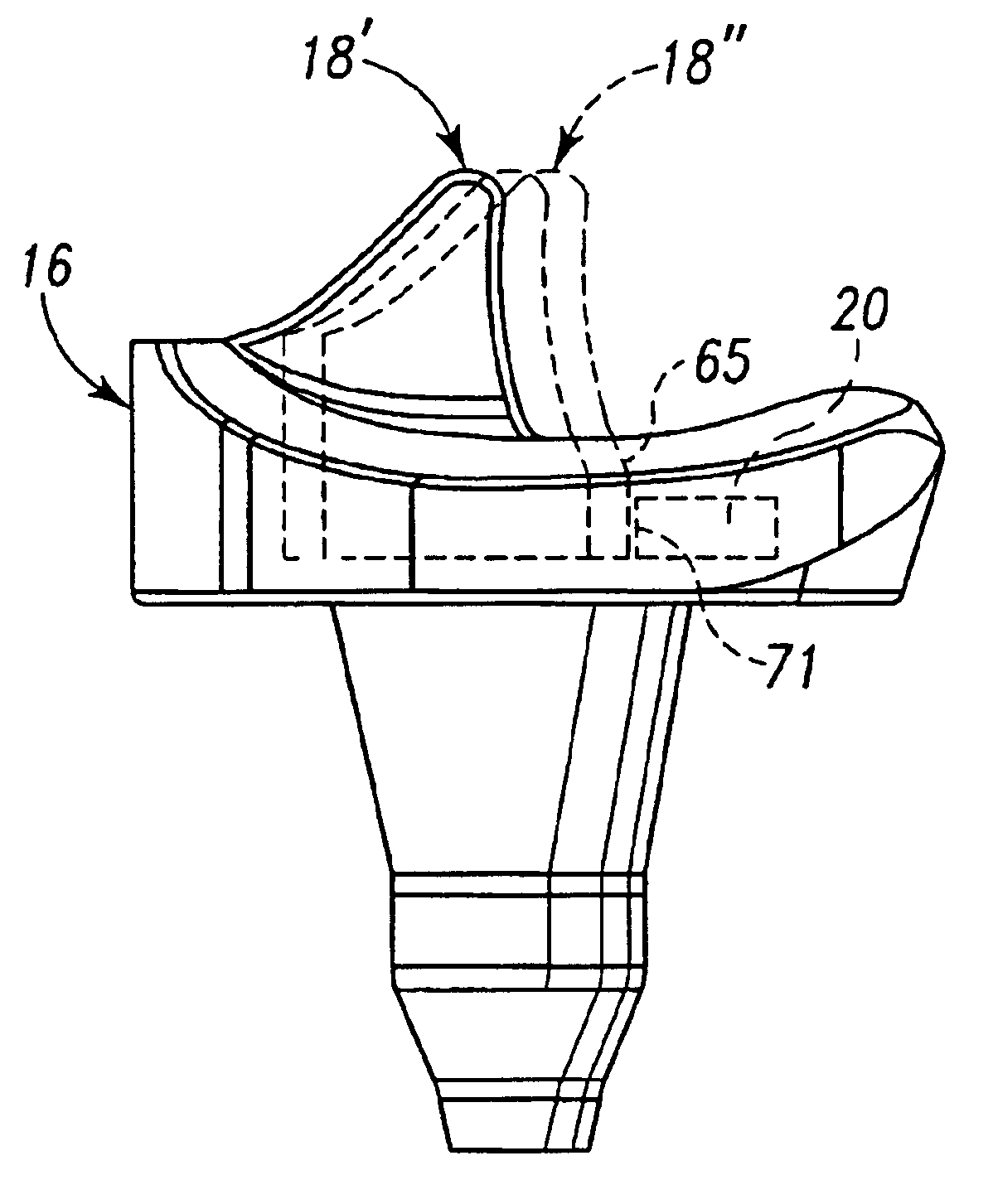
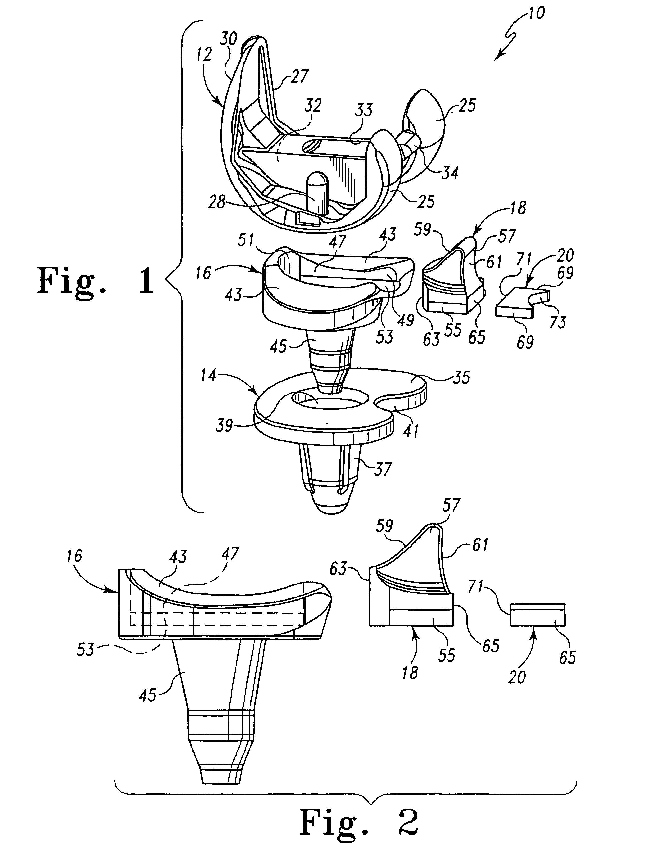
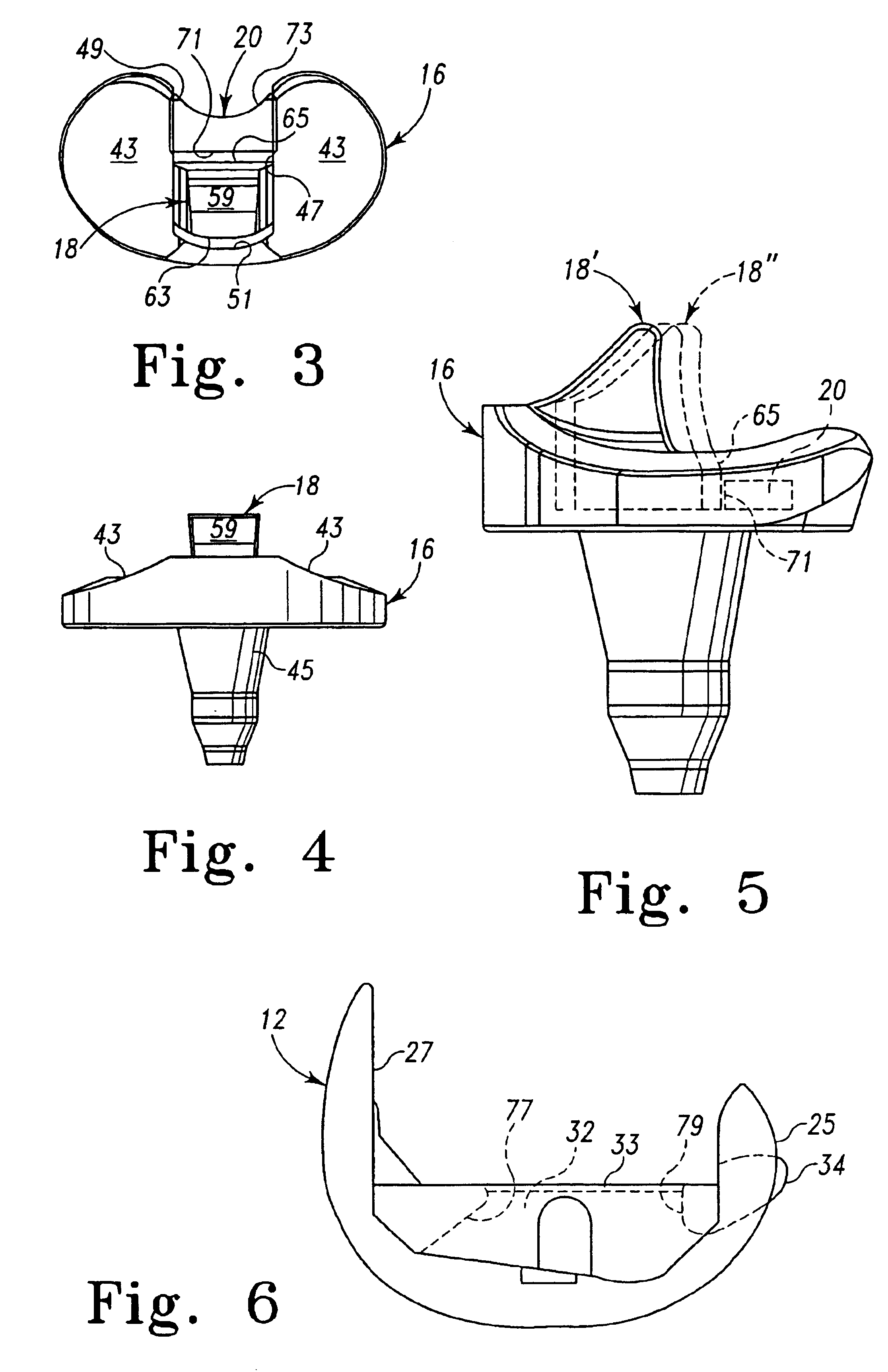
[0026]Referring first to FIG. 1, a modular joint prosthesis 10 is depicted that comprises a first joint component 12, a second joint component 14 and an intermediate joint component 16. From the perspective of a knee prosthesis, the first joint component 12 can be referred to as the femoral component, the second joint component 14 as the tibial component, and the intermediate joint component 16 as the meniscal c...


PUM


Abstract

A knee joint prosthesis includes a femoral component for engaging the femur having an articular surface and a recess within the articular surface, and a tibial component for engaging the tibia with a bore, and a meniscal component comprising a rotation pin configured for rotatable mounting within the bore of the tibial component. The meniscal component also includes a bearing surface for sliding contact with the articular surface of the femoral component and an elongated channel defined amid the bearing surface. A stabilizing post is provided that includes a base slidably mounted with the elongated channel and a spine post projecting from the base through the channel and into the recess when the articular surface is in contact with said bearing surface. The stabilizing post thus slides within the channel when contacted by the interior of the recess in the femoral component.

Description

[0001]This application is a continuation of application Ser. No. 10 / 185,492, filed on Jun. 28, 2002, now abandoned, the disclosure of which is hereby totally incorporated by reference in its entirety.BACKGROUND OF THE INVENTION[0002]The present invention relates to prosthetic joints, and particularly to a prosthesis for the knee joint.[0003]Implantable knee prostheses for diseased and / or damaged knees typically include three components, namely a femoral component, a tibial component and a meniscal component. The femoral component may also include a patellar element, or a separate patellar component may be provided. The prosthesis components are generally configured to restore or emulate as much of the natural motion of the knee joint as possible. The selection of the particular prosthesis components is usually dictated by the condition of the patient's knee. For instance, the condition of the distal end of the femur and proximal end of the tibia, as well as the patency of the surrou...

Claims


Application Information

Patent Timeline
Patent Type & Authority Patents(United States)
IPC IPC(8): A61F2/38
CPCA61F2/3868A61F2/3886
Inventor WYSS, JOSEPH
Owner DEPUY ORTHOPAEDICS INC
Why Eureka
Try Eureka