Twin-wire line

a technology of twin wires and wires, applied in the direction of communication cables, line-transmission details, cables, etc., to achieve the effect of reducing the quantity of equipment and the number of spans, increasing the passband, and reducing the cost of equipmen

Inactive Publication Date: 2005-08-09
BOGOMOLNY T
View PDF3 Cites 3 Cited by
  • Summary
  • Abstract
  • Description
  • Claims
  • Application Information

AI Technical Summary

Benefits of technology

[0011]Accordingly, it is an object of the present invention to increase the passband, transmission speed, carrying capacity, span length, to using the thinnest wire gauge, to reduce the quantity of equipment and the number of spans, and/or to im

Problems solved by technology

However, this all now-known means in generally is insufficiently for the following increasing the twin-pair line passband, span length, etc. accordingly of an object of the

Method used


Image

  • Twin-wire line
  • Twin-wire line
  • Twin-wire line

Examples


Embodiment Construction

[0069]The twin-wire line with the present invention is formed and run in the following manner.

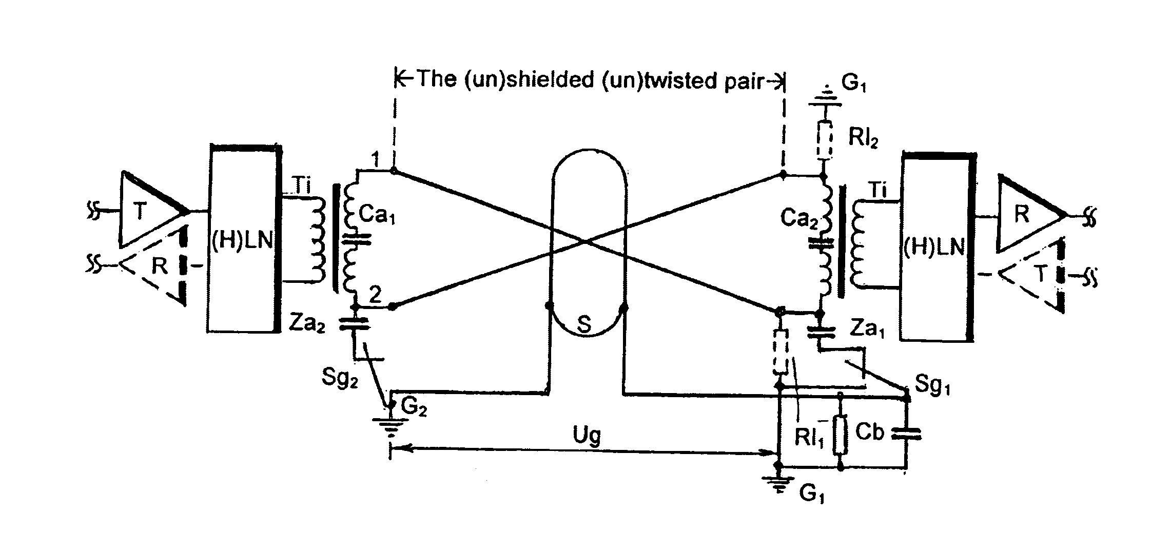
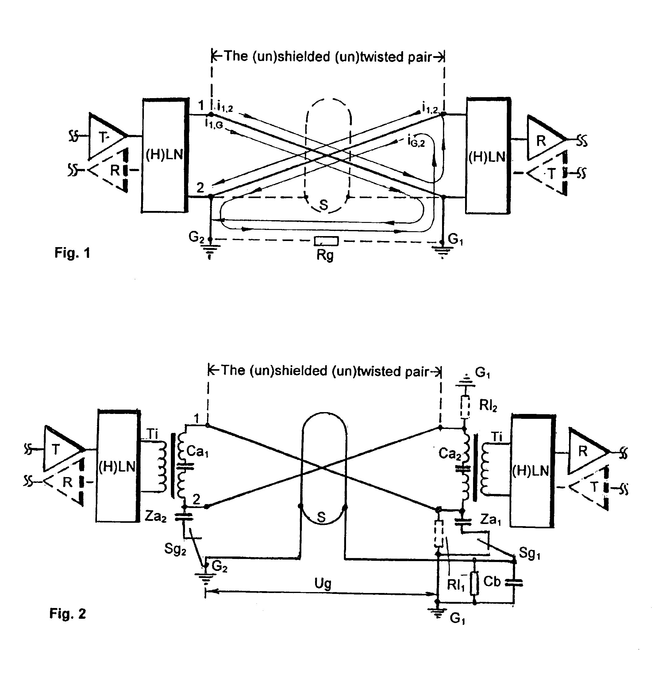
[0070]To achieve the objective of present invention in the proposed twin-wire line spans by means of the introduced grounds G1, G2, respectively the one wire 1 at the one end of the (un)shielded (un)twisted pair span, and the other wire 2 at the apposite pair span end (FIG. 1), the signal is first simplex / (half-)duplex passed in parallel both as usual directly over the existing pair wires 1, 2 and in the bypass over the same wires 1, 2 of the same pair and the ground return path G1-G2.

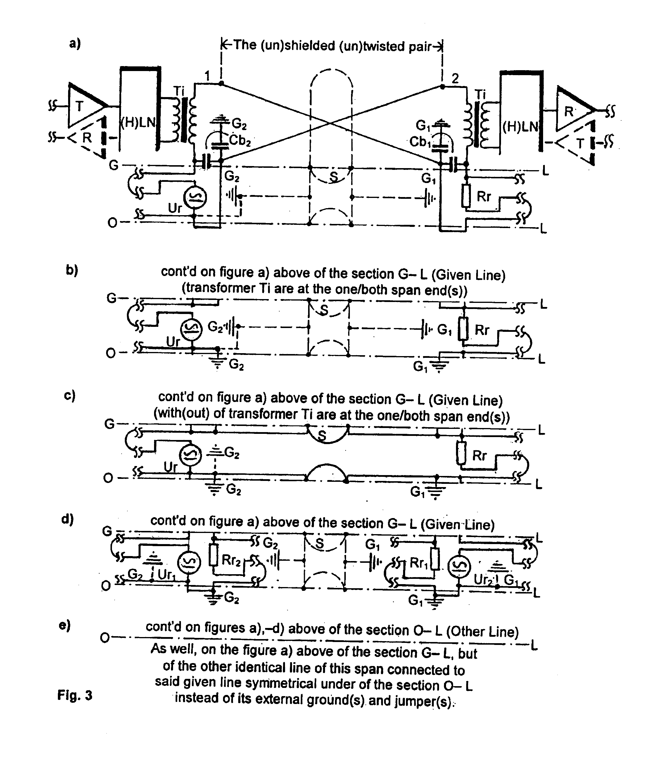
[0071]By the zero-length of the improved span(s) the proposed line is short-circuited by the grounds G1 of the one wire 1 and G2 of the other wire 2 entered at the apposite span ends. The transmission started with the wave-process making with the span(s) length and signal(s) frequencies growing. By the span length more than 5,000-10,000 feet (1.5-3 km) the lower cutoff frequency rate of the passband it is roug...


PUM


Abstract

A twin-wire line over (un)shielded (un)twisted pair for simplex and duplex analog and digital single- and multi-span single- and multi-channel local and long-distance cable communications comprising on every improved span the repeatedly in turn grounded pair wires at first the one wire, than the other wire etc. again the next from the pair wires are with the step length between said grounds are roughly and more of a fourth of the wave length of the low-frequency rate of the passband, and at least neither more than one time so grounded each pair wire of an improved span to increase several times the passband, span length, reduce the quantity of equipment and number of spans, improve, simplify and reduce cost of them and cable communications by means of reduce the currently in force passband attenuation per unit length of an existing pair of the existing/laying cables below of the universally known rated its self-value, reduced by means of the introduced parallel signal transmitting both as usual directly over the existing pair wires and in bypass over the same wires of the same pair and the ground return path accomplish as the external (frame) grounds, an AC network, a pair shield, and even a metallic cable sheath.

Description

BACKGROUND OF THE INVENTION[0001]The present invention related to simplex and (half-)duplex analog and digital single- and multi-span single- and multi-channel local and long-distance cable communications over (un)shielded (un)twisted pair for transmission of data, telephone, television, internet, and other coded / modulated / any signals.[0002]The twin-wire lines over (un)shielded (un)twisted pair—the most common type of transmission media—is universally known [Newton's, “Telecom dictionary”, 15th edition, pp. 709, 823, 835]. In general the twin-wire lines over unshielded twisted pair is the only type of all subscriber lines of all cable communications.[0003]The most nearest by a technical essence is the universally known twin-wire line over (un)shielded (un)twisted pair with the load-networks connected the pair end(s) of span(s) of cable communications directly by a simplex and via a hybrid [ibid, p. 387] by a duplex to the in / out stage / s of the line equalizers [ibid, p. 283], repeate...

Claims


Application Information

Patent Timeline
IPC IPC(8): H01B11/02H04B3/14
CPCH04B3/144
Inventor STRIZHEVSKIY, NAUM
Owner BOGOMOLNY T
Why Eureka
Try Eureka