Wire pass through seal with grommets

a technology of grommets and wires, applied in the direction of machine supports, manufacturing tools, insulation bodies, etc., can solve the problems of difficult to achieve the desired positioning of the conductor ends relative to the opposite side of the shield, difficult to seal across the shield, and ingress of air, water and dirt across the shield to the dry side of the shield. achieve the effect of sealing interconnection

Inactive Publication Date: 2005-08-09
KEY CAPITAL +2
View PDF6 Cites 23 Cited by
  • Summary
  • Abstract
  • Description
  • Claims
  • Application Information

AI Technical Summary

Benefits of technology

[0010]Another object is a provision of a grommet of the foregoing character which enables the sealing interengagement between electrical wires, a wiring harness, or the like and a shield component t...

Problems solved by technology

The mere provision of slits in the shield for wires makes sealing across the shield extremely difficult, whereby the ingress of air, water and dirt across the shield to the dry side thereof remains a problem.
While adequate sealing is achieved with the corrugated pocket arrangement described above, desired positioning of the conductor ends relative to the opposite sides of the shield is difficult to achieve because of the presence of the adhesive about the opening through which the conductors are passed.
Further, if it becomes necessary to remove and replace the ...

Method used


Image

  • Wire pass through seal with grommets
  • Wire pass through seal with grommets
  • Wire pass through seal with grommets

Examples


Embodiment Construction

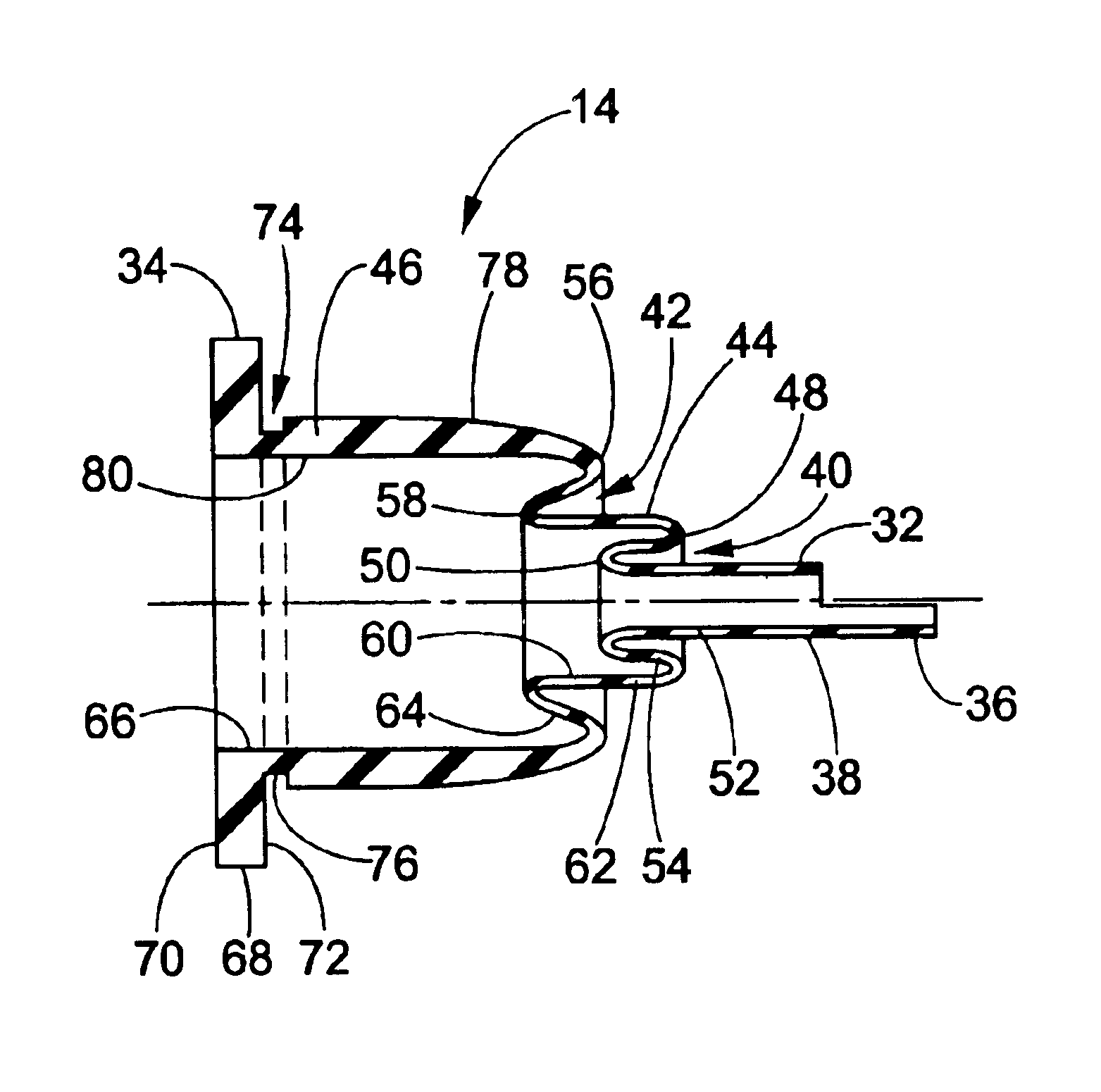
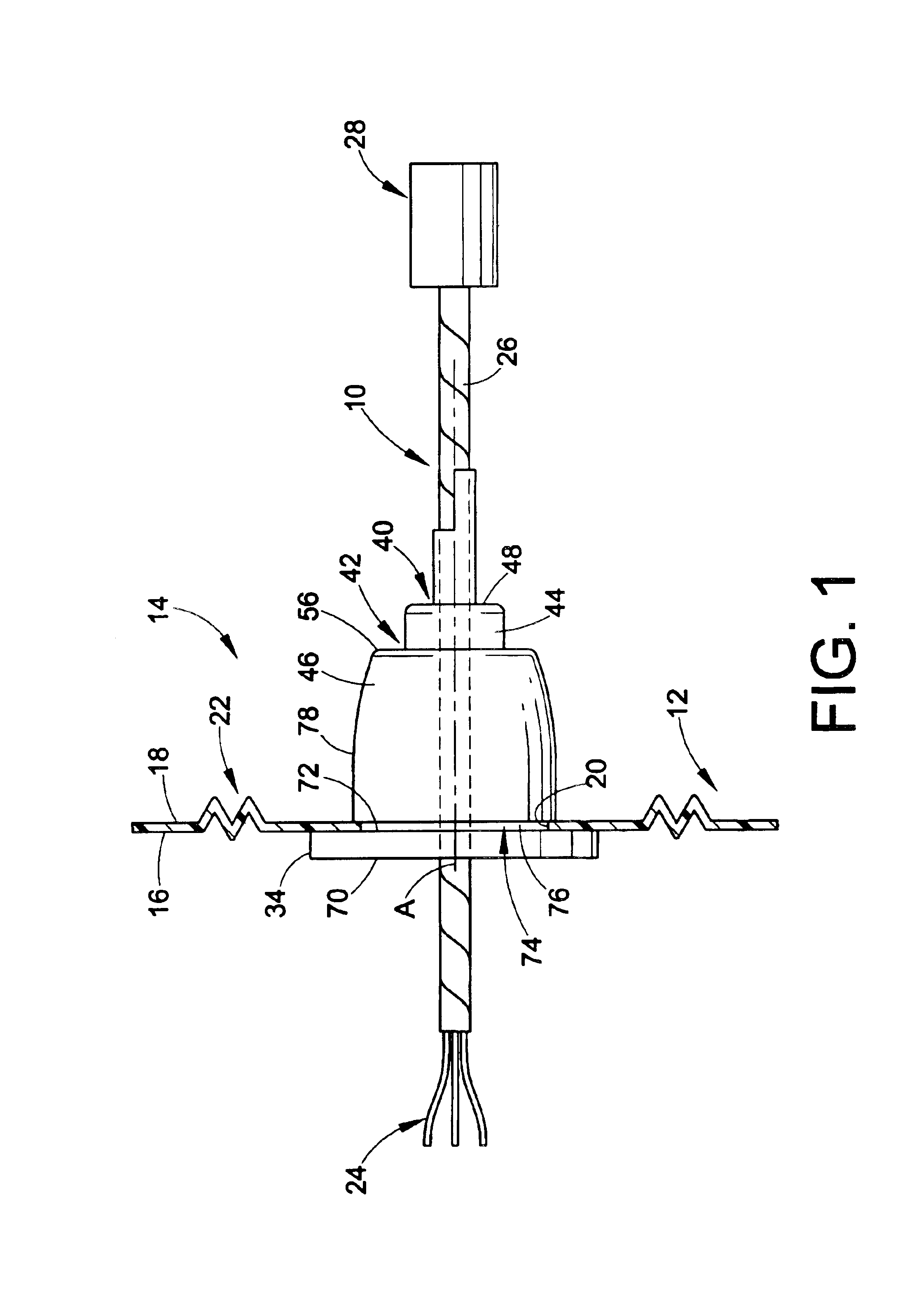
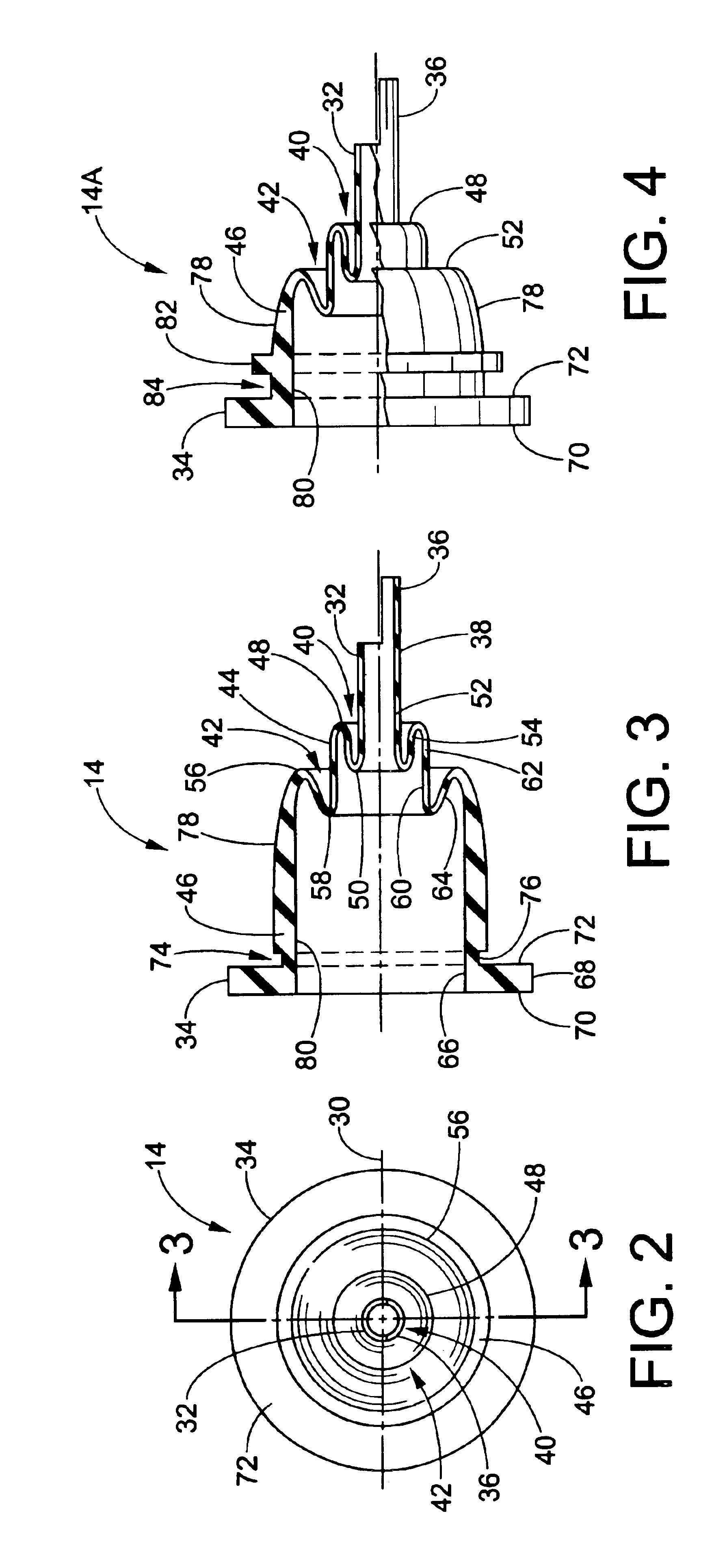
[0016]Referring now in greater detail to the drawings, wherein the showings are for the purpose of illustrating preferred embodiments of the invention only, and not for the purpose of limiting the invention, FIG. 1 illustrates a wiring harness 10 mounted on a watershield 12 by means of a grommet 14 which is also shown in FIGS. 2 and 3 of the drawing. Watershield 12 is of a suitable plastic material, such as polyethylene, and has wet and dry sides 16 and 18, respectively. The shield is provided with an opening 20 having an axis A and, preferably but not necessarily, opening 20 is surrounded by a plurality of corrugations 22 similar to those described in the aforementioned patents and which provide added flexibility for the wiring harness mounting. Wiring harness 10 comprises a plurality of electrical conductors 24 wrapped in electrical tape 26 and having an electrical connector 28 on the end thereof which is on the dry side of the shield. It will be appreciated that connector 28 can ...


PUM


Abstract

A tubular grommet for sealing a conductor relative to a substrate having opposite sides and an opening therethrough for the conductor has axially opposite ends, one of which sealing engages with the conductor and the other of which is radially spaced from the conductor, diametrically larger than the opening through the substrate, and includes a radially outwardly extending peripheral flange for engaging against the substrate when the grommet is mounted thereon. A wall between the ends includes first and second re-entrant wall portions facing the one end, and the grommet can be provided with a recess in the wall adjacent the flange for receiving the peripheral edge of the opening through the substrate and/or can be adhesively bonded to the substrate by an adhesive interposed between the flange and substrate.

Description

[0001]This application is based on U.S. Provisional Patent Application Ser. No. 60 / 417,391 filed Oct. 9, 2002 and claims the benefit thereof.BACKGROUND OF THE INVENTION[0002]This invention relates to the art of seals and, more particularly, to a grommet for sealing electrical conductors extending through an opening between wet and dry sides of a substrate such as a watershield component.[0003]The present invention finds particular utility in connection with sealing electric wires in a wiring harness extending through a watershield mounted on the inner panel of a vehicle door. Accordingly, the invention will be illustrated and described in detail herein in connection with such use. At the same time, as will become apparent hereinafter, it will be appreciated that the invention is applicable to the sealing of wires relative to the opposite sides of other substrates such as panels, plate components, or the fire wall of a vehicle, for example.[0004]It is known, as shown in commonly assi...

Claims


Application Information

Patent Timeline
IPC IPC(8): H02G3/22
CPCH02G3/22Y10T16/063
Inventor SHIMOLA, GREGORY W.CELLURA, DANIEL JOSEPH
Owner KEY CAPITAL
Why Eureka
Try Eureka