Photomultiplier tube

a technology of photomultiplier and tube, which is applied in the direction of photoelectric discharge tube, electron multiplier details, instruments, etc., can solve the problems of vibration and degradation over time, dynodes to rattle in the holes, and the direction of rotational rattling tends to occur in the direction of the support portion,

Inactive Publication Date: 2005-08-09
HAMAMATSU PHOTONICS KK
View PDF26 Cites 21 Cited by
  • Summary
  • Abstract
  • Description
  • Claims
  • Application Information

AI Technical Summary

Benefits of technology

[0011]With this construction, the first and second support portions are formed at a prescribed angle in relation to each other. Therefore, rattling of the dynode in the direction of rotation about one support portion is restricted by the other support portion. Even when rattling is generated due to clearance, play, or the like provided for inserting the dynode into the through-holes of the base plate, the directivity and play of the rattling in one support portion is restricted by the other support portion, thereby enabling the dynodes to be reliably and fixedly supported.
[0015]With this construction, the side surface portions are provided on both ends of the secondary electron emitting surface in the lengthwise direction, thereby preventing electrons from colliding directly with the base plate and charging up the same. The electron trajectories converge on the inner surface due to the potential on both side surface portions. Further, since the side surface portions are disposed one on both lengthwise ends of the secondary electron emitting surface in the dynode, the first support portions are provided on both side surface portions, and the second support portions form a prescribed angle with the first support portions, rattling relative to the first and second support portions is restrained by the side surface portions, thereby more effectively preventing rattling.
[0018]In the photomultiplier tube of the present invention, it is possible to provide a shielding plate between the dynode of the first stage and the dynodes of the (n−3)th through nth stages.
[0019]This construction can prevent light and ions generated when electrons collide with dynodes of the (n−3)th through nth stages from traveling toward the photocathode.

Problems solved by technology

For photomultiplier tubes used in high-temperature, high-vibration environments, as in oil exploration, noise due to vibrations and degradation over time are problems, since accurate operations are required while drilling deep underground.
However, when supporting each end of a dynode with a single support portion, rattling tends to occur in the direction of rotation about the support portions.
HEI 9-180670, if clearance is provided to enable the dynodes to be easily inserted into the holes, the plate-shaped concave plate portions and the top and bottom support plate portions deform when exposed to severe vibrations, causing the dynodes to rattle severely in the holes.
Hence, the dynodes cannot be reliably fixed.

Method used


Image

  • Photomultiplier tube
  • Photomultiplier tube
  • Photomultiplier tube

Examples


Embodiment Construction

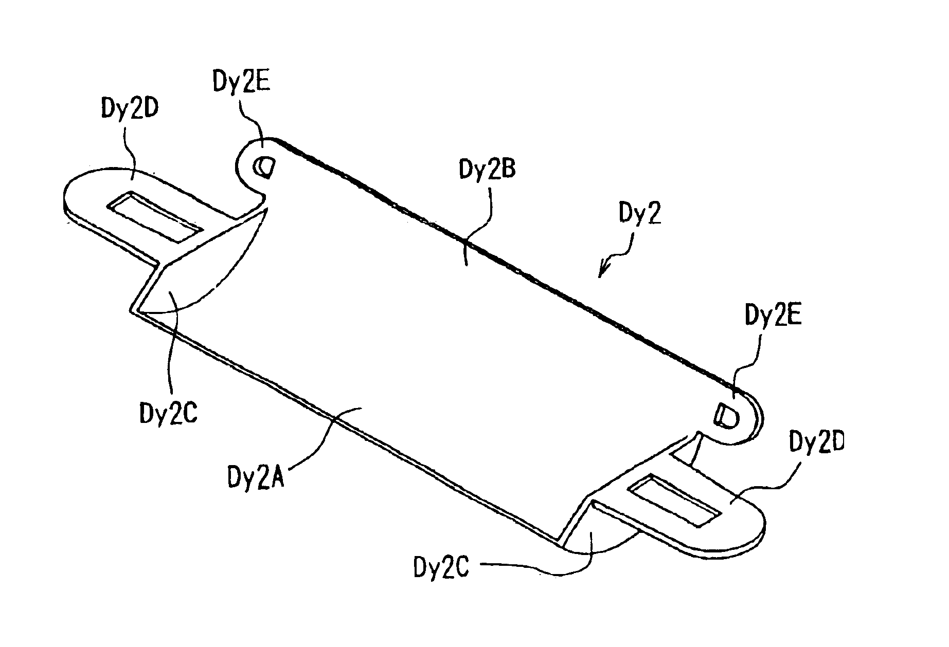
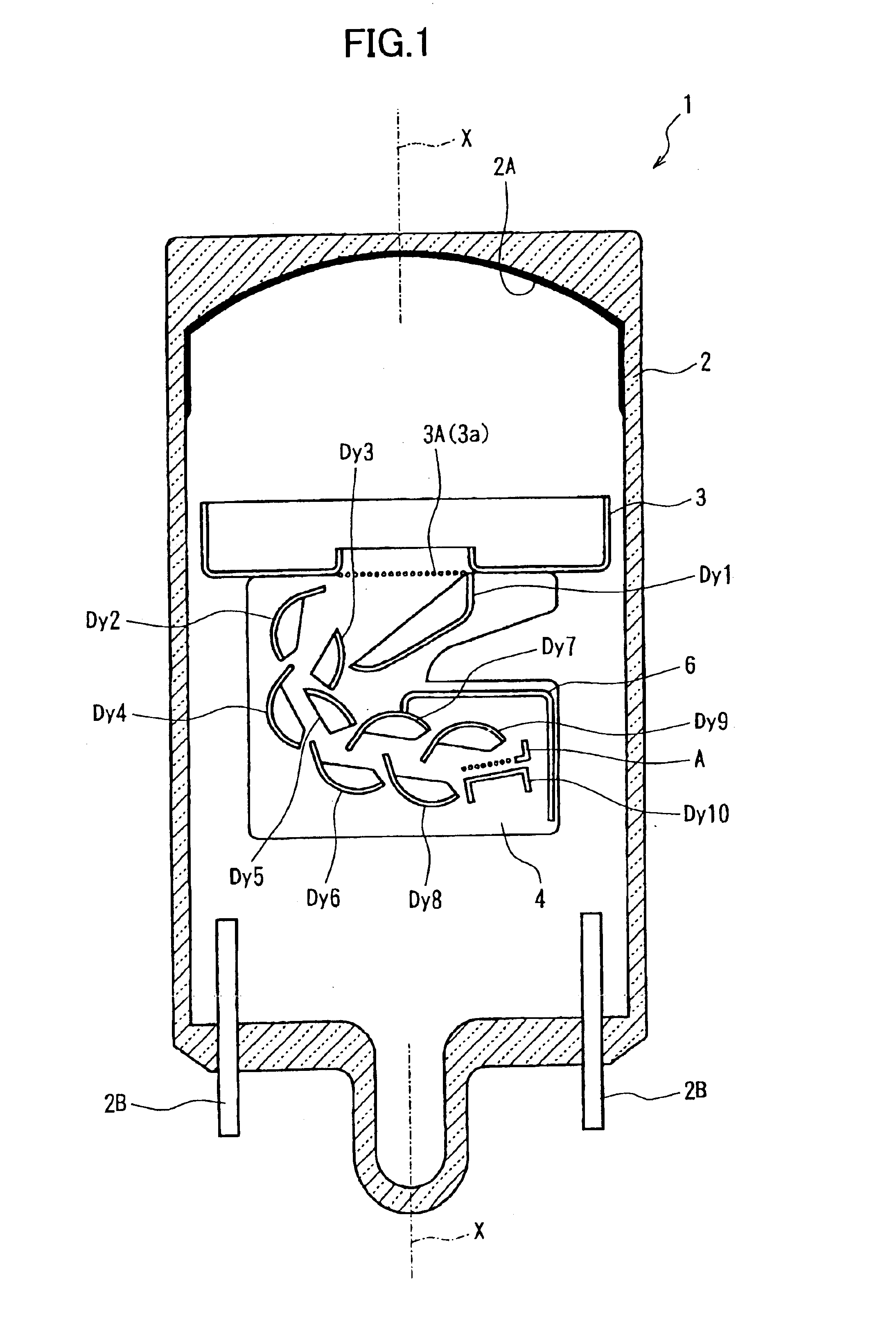
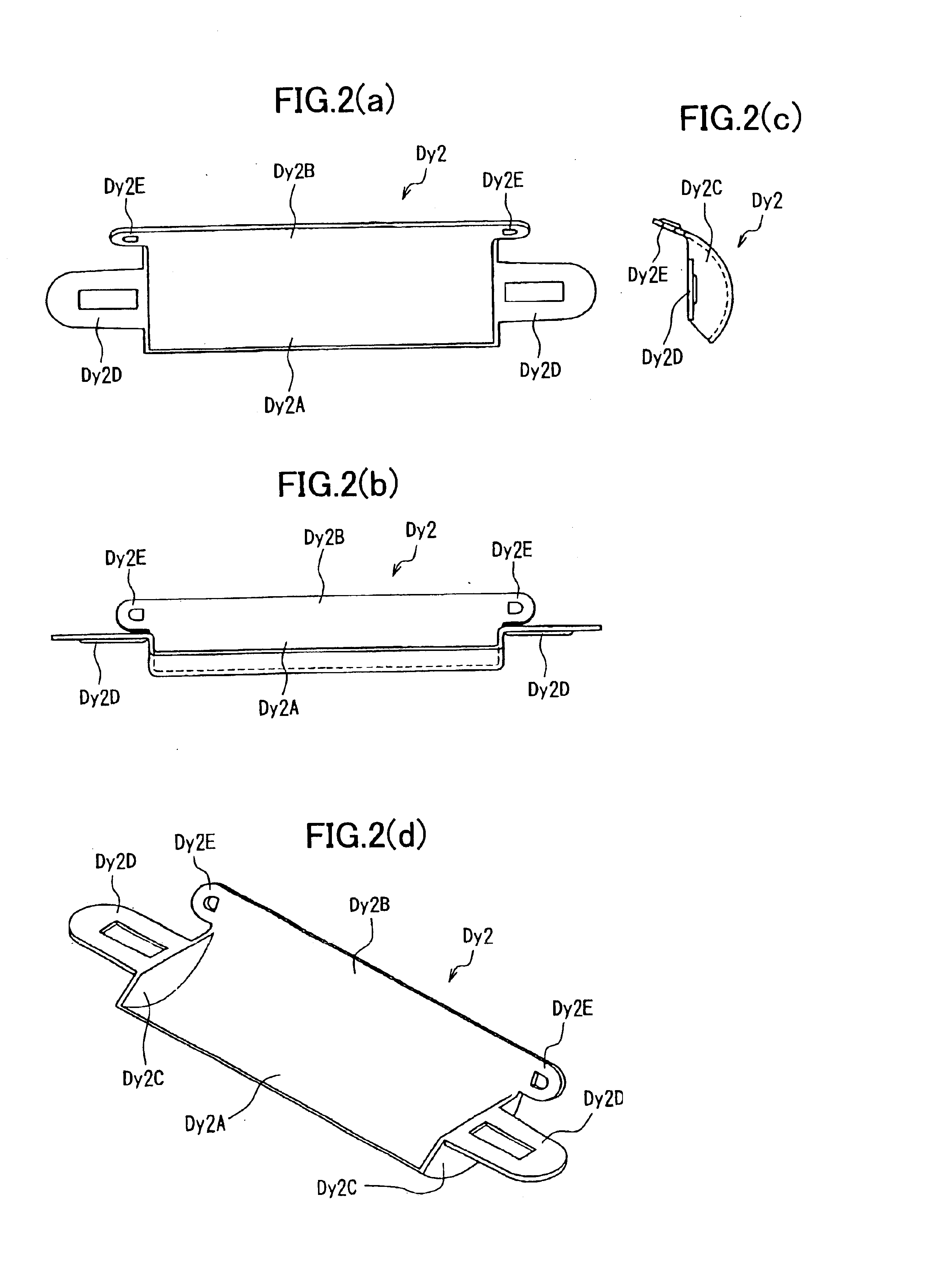
[0026]A photomultiplier tube according to an embodiment of the present invention will be described while referring to FIGS. 1 through 6. A photomultiplier tube 1 according to the embodiment includes a tube-shaped vacuum vessel 2 having a tube axis X. FIG. 1 is a cross-sectional view of the photomultiplier tube 1 cut along the tube axis X. The tube-shaped vacuum vessel 2 is formed of Kovar glass or a like material.

[0027]Both ends of the tube-shaped vacuum vessel 2 along the tube axis X are closed. One end has a planar shape. A photocathode 2A is formed on the inner surface of this planar end for emitting electrons in response to incident light. The photocathode 2A is formed by reacting an alkali metal vapor with antimony that has been pre-deposited on the inner surface of the end. A plurality of lead pins 2B are provided on the other end of the tube-shaped vacuum vessel 2 for applying prescribed potentials to dynodes Dy1-Dy10 and an anode A. FIG. 1 shows only two of the lead pins 2B ...


PUM


Abstract

A photomultiplier that prevents rattling between the dynodes and the base plates, the parts being fixed securely to achieve excellent vibration resistance. The dynode of the second stage (Dy2) includes a curved surface (Dy2A) having an arcuate cross-section and a flat surface (Dy2B) formed continuously and flush with the curved surface. The curved surface (Dy2A) and flat surface (Dy2B) make up the secondary electron emitting surface. Side walls (Dy2C) erected from the curved surface (Dy2A) are formed through a pressing process on either lengthwise end of the curved surface (Dy2A). First ear portions (Dy2D) extend outward from both side walls (Dy2C). Second ear portions (Dy2E) extend outward from both lengthwise ends of the flat surface (Dy2B). The first and second ear portions (Dy2D and Dy2E) are not parallel to each other but form a fixed angle.

Description

TECHNICAL FIELD[0001]The present invention relates to a photomultiplier tube, and particularly to a photomultiplier tube with excellent vibration resistance.BACKGROUND ART[0002]For photomultiplier tubes used in high-temperature, high-vibration environments, as in oil exploration, noise due to vibrations and degradation over time are problems, since accurate operations are required while drilling deep underground. The electrode in the photomultiplier tube must be securely and fixedly supported, since noise generated during vibrations is caused mainly by displacement of the electrode within the photomultiplier tube.[0003]When forming an electron multiplying portion in a conventional photomultiplier tube, wherein dynodes of a plurality of stages are inserted into and supported by two ceramic base plates, individual support portions are formed on either end of each dynode, and corresponding individual linear portionslits are formed in each ceramic base plate. The support portions are su...

Claims


Application Information

Patent Timeline
Patent Type & Authority Patents(United States)
IPC IPC(8): H01J43/20H01J43/00
CPCH01J43/20
Inventor ISHIZU, TOMOHIROFUJITA, TETSUYA
Owner HAMAMATSU PHOTONICS KK
Why Eureka
Try Eureka