
Method and apparatus for making measurements of accumulations of magnetically susceptible particles combined with analytes

a technology of magnetically susceptible particles and analytes, applied in the field of sensing the presence of magnetic particles, can solve the problems of radioactive methods presenting health and disposal problems, methods are also relatively slow, fluorescent or phosphorescent techniques are limited in their quantitative accuracy and dynamic range, and achieve the effect of accurate estimation of the magnetic content of the sampl

Inactive Publication Date: 2005-08-09
QUANTUM DESIGN
View PDF4 Cites 84 Cited by
  • Summary
  • Abstract
  • Description
  • Claims
  • Application Information

AI Technical Summary

Benefits of technology

[0017]The signal amplitude is modulated by moving the sample with respect to the sensor. This allows the rejection of signals due solely to imbalance of the sensor, non-uniformity of the drive field, cross-talk in the circuitry, or any other source of apparent signal which is not due to the sample itself. The digitized shape of the signal amplitude with respect to the sample position is compared to the theoretical response shape using appropriate curve-fitting techniques, providing a very accurate estimate of the magnetic content of the sample in the face of inherent instrument noise and drift.

Problems solved by technology

For example, radioactive methods present health and disposal problems.
The methods are also relatively slow.
Fluorescent or phosphorescent techniques are limited in their quantitative accuracy and dynamic range because emitted photons may be absorbed by other materials in the sample.
There are several substantial difficulties with this approach, however.
This procedure makes the measurements unacceptably tedious.
The general complexity of SQUIDs and cryogenic components renders them generally unsuitable for use in an inexpensive desktop instrument.
Even a design based on so-called “high Tc” superconductors would not completely overcome these objections, and would introduce several new difficulties.
These approaches are all limited in that they rely on converting an intrinsically magnetic effect into a mechanical response.

Method used


Image

  • Method and apparatus for making measurements of accumulations of magnetically susceptible particles combined with analytes
  • Method and apparatus for making measurements of accumulations of magnetically susceptible particles combined with analytes
  • Method and apparatus for making measurements of accumulations of magnetically susceptible particles combined with analytes

Examples


Embodiment Construction

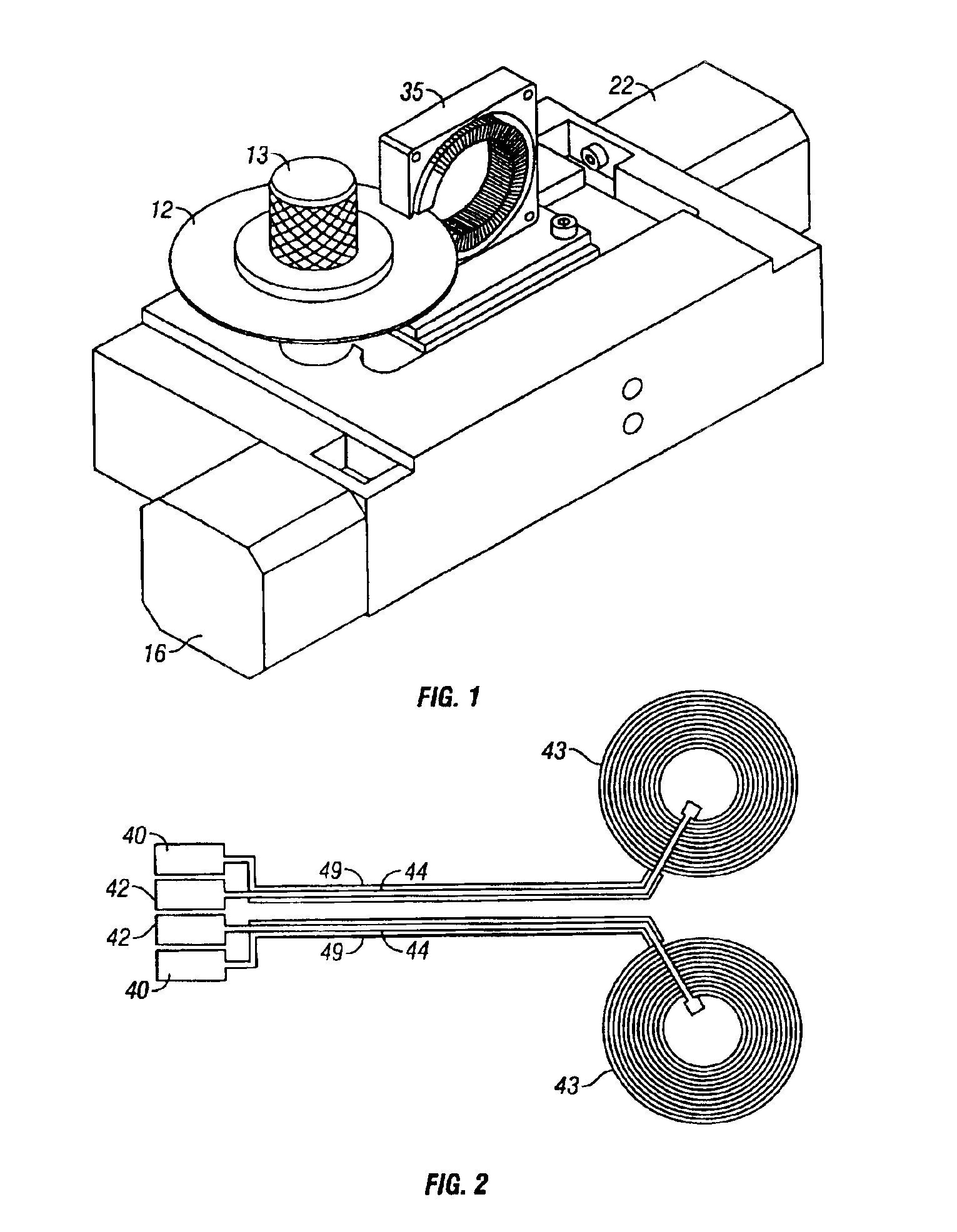
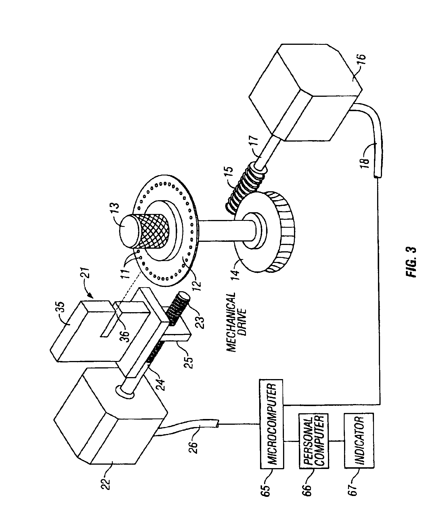
[0031]Referring now to the drawing, and more particularly to FIGS. 1 and 3 thereof, there is shown a preferred embodiment of the invention.

I. Reader Module

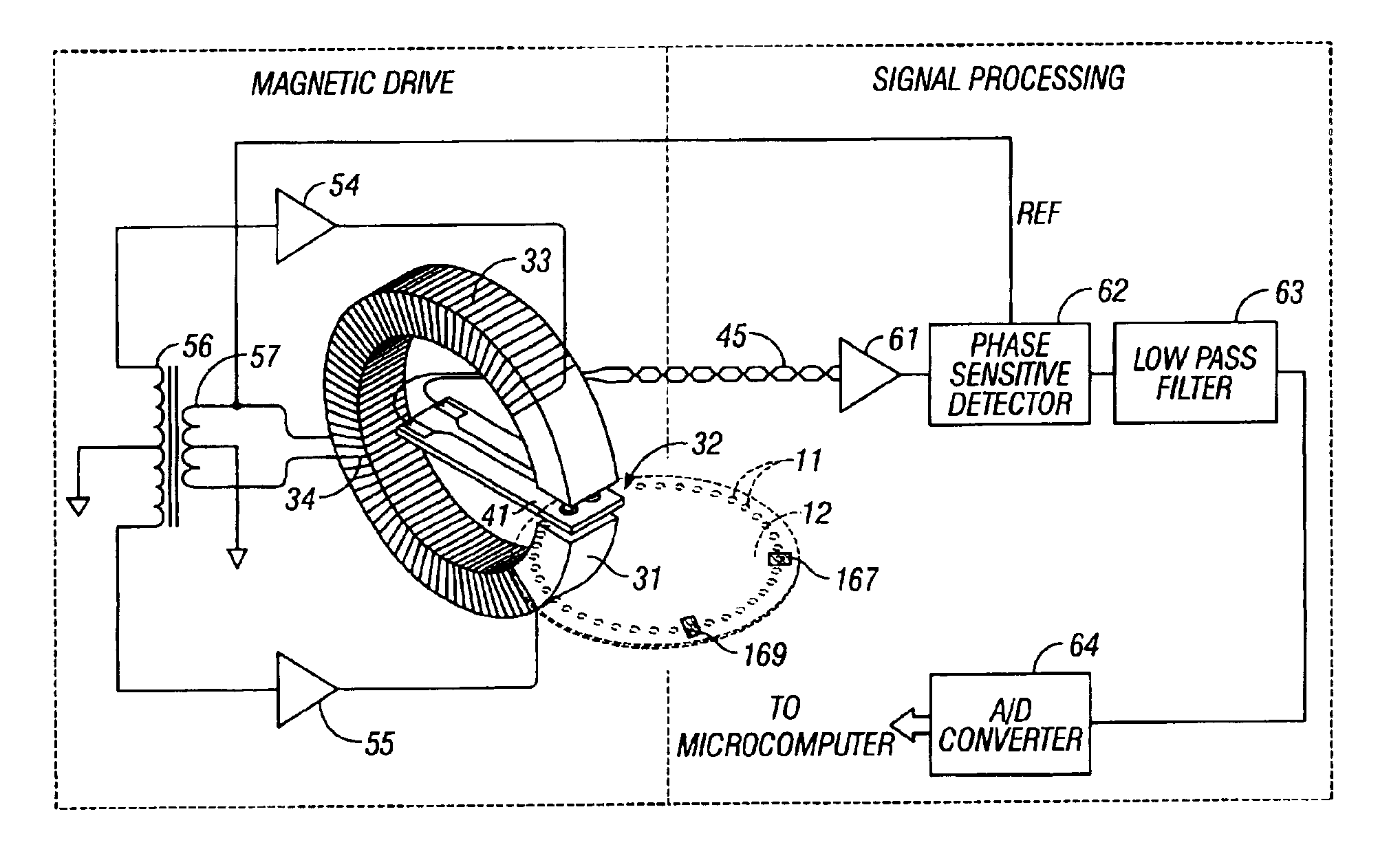
[0032]The reader module includes several distinct subsystems. These include: a sample holder with a motion control. The magnetic bound complex samples for measurement reside on the holder, and the same also provides the necessary relative motion within the system. A magnetizer or magnetic field source applies the excitation signals to the samples. Sensors, such as sensing coils, act as the signal pick-up for the signals generated in the samples. A drive circuit supplies the drive current to the coils of the magnetic field source. An amplifier / phase detector / digitizer is coupled to the sensor to receive and process the output signals therefrom. A microcomputer chip provides two-way communication between the external personal computer (PC) and the reader module.

A. Sample Motion Control

[0033]Magnetic particles are coupled to analyte ...


PUM


Abstract

An apparatus is provided for quantitatively measuring samples whose amount or other characteristic quality is to be determined. The samples are arranged in a predefined pattern and are excited in a magnetic field. The magnetizations of the magnetic particles are thereby caused to oscillate at the excitation frequency in the manner of a dipole to create their own fields. These fields are inductively coupled to at least one substantially flat sensor such as sensing coils fabricated in a gradiometer configuration.

Description

CROSS REFERENCE TO RELATED APPLICATIONS[0001]This is a continuation application of U.S. patent application Ser. No. 09 / 911,934 filed on Jul. 23, 2001 now U.S. Pat. No. 6,597,176, entitled “Method And Apparatus For Making Measurements Of Patterns Of Magnetic Particles In Lateral Flow Membranes And Microfluidic Systems” which is a divisional patent application of U.S. patent application Ser. No. 09 / 451,660 filed on Nov. 30, 1999, now U.S. Pat. No. 6,437,563 entitled “Method and Apparatus for Making Measurements of Accumulations of Magnetic Particles”, which is a continuation-in-part patent application of U.S. patent application Ser. No. 08 / 975,569 filed on Nov. 21, 1997, now U.S. Pat. No. 6,046,585 entitled “Method and Apparatus for Making Quantitative Measurements of Localized Accumulations of Targets Particles Having Magnetic Particles Bound Thereto”.BACKGROUND OF THE INVENTION[0002]1. Field of the Invention[0003]This invention relates generally to sensing the presence of magnetic p...

Claims


Application Information

Patent Timeline
IPC IPC(8): G01N33/483G01N33/487G01R33/12G01N35/00G01N27/72G01N33/543G01N33/553
CPCB82Y15/00B82Y25/00G01N27/745G01R33/12G01N35/0098Y10S977/773Y10S977/838Y10S977/96
Inventor SIMMONDS, MICHAEL BANCROFTJENSEN, KURT GORDONDIEDERICHS, JOST HERMANNBLACK, RANDALL CHRISTOPHER
Owner QUANTUM DESIGN
Features
  • Generate Ideas
  • Intellectual Property
  • Life Sciences
  • Materials
  • Tech Scout
  • Unparalleled Data Quality
  • Higher Quality Content
  • 60% Fewer Hallucinations
Learn More