Failsafe for differential circuit based on current sense scheme

a current sense scheme and differential circuit technology, applied in logic circuit coupling/interface arrangement, instruments, pulse techniques, etc., can solve problems such as inability to provide output after reversed circuits

Inactive Publication Date: 2005-08-09
SEMICON COMPONENTS IND LLC
View PDF7 Cites 4 Cited by
  • Summary
  • Abstract
  • Description
  • Claims
  • Application Information

AI Technical Summary

Problems solved by technology

If the positive currents received by the two diode connected CMOS transistors were equal, reversing them would not provide an output.

Method used


Image

  • Failsafe for differential circuit based on current sense scheme
  • Failsafe for differential circuit based on current sense scheme
  • Failsafe for differential circuit based on current sense scheme

Examples


Embodiment Construction

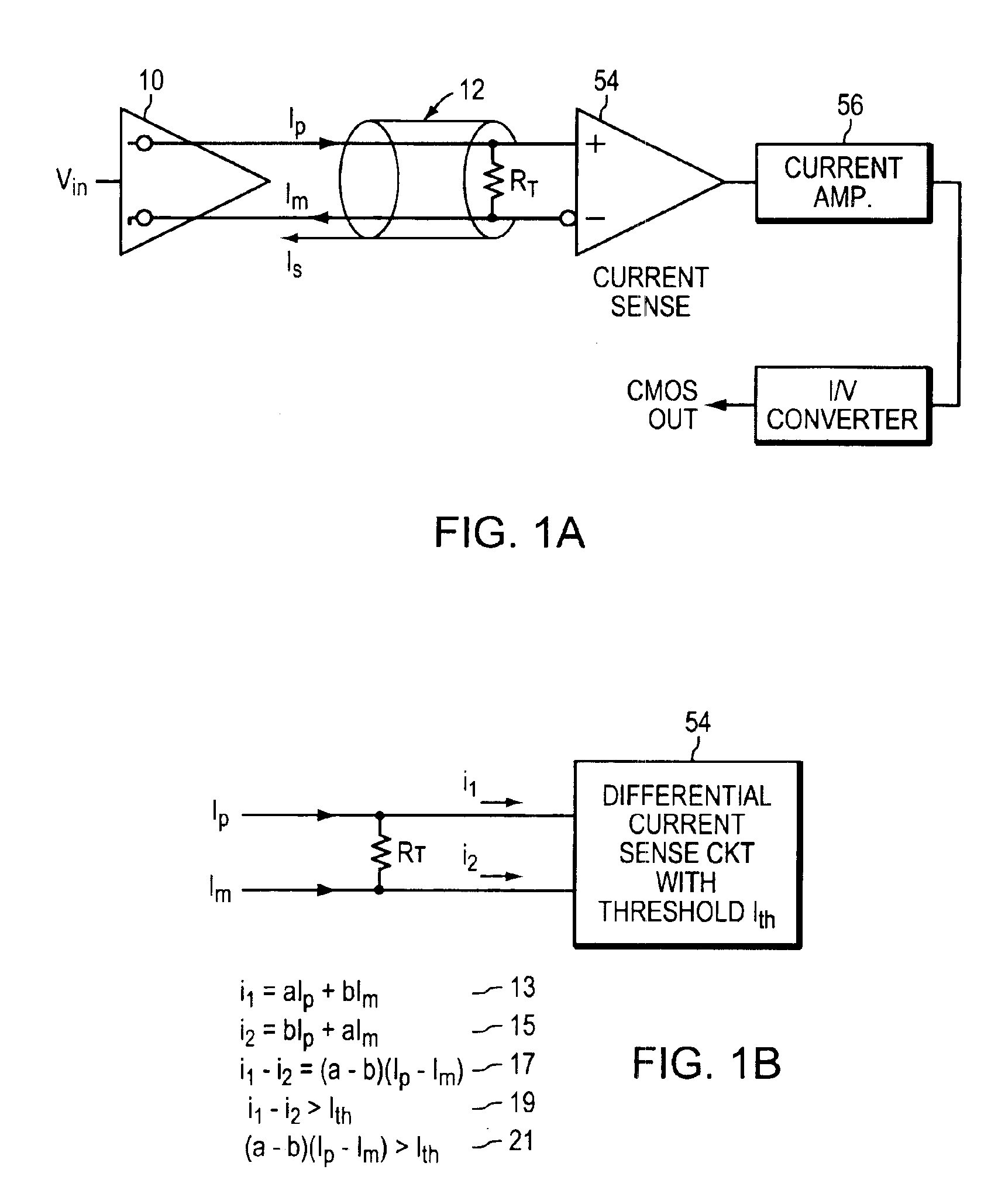
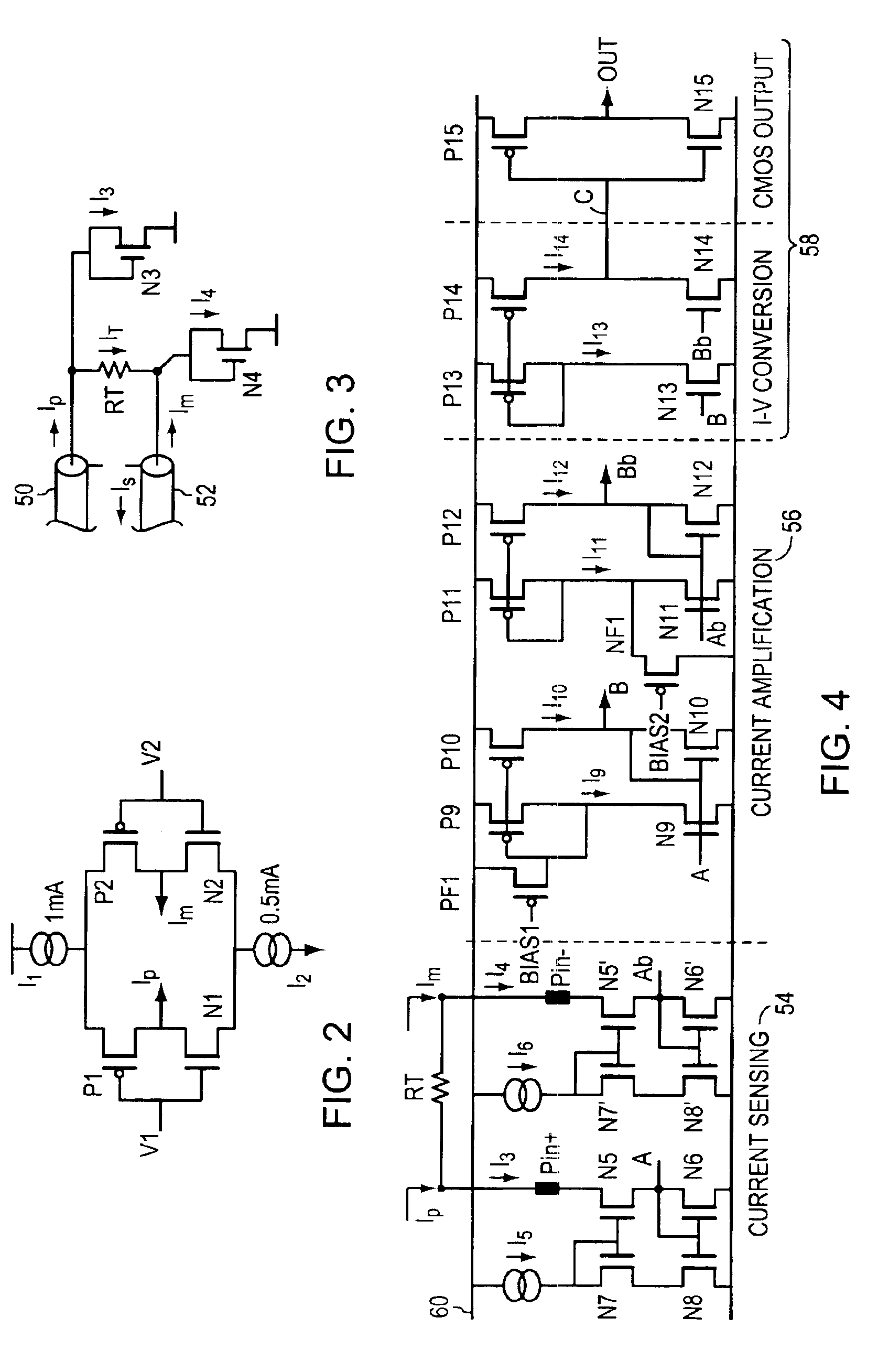
[0025]EMBODIMENT FIG. 1A shows a diagram of a preferred embodiment of the present invention. An input signal, Vin controls and selects output current signals Ip and Im that are driven 10 into a transmission line 12. The driver 10 is a current driver with a high output impedance. In practice there may be a single twisted pair or two transmission lines, but as discussed below since Ip and Im are not equal, there will be a return current that is absorbed by the current sense amplifier when a twisted pair is used or that travels through a shield if present. Transmission lines are not fundamental to the practical use of the present invention, but if not used some noise friendly path must be provided for the return current Is. In one logic state Ip is a positive current out into a first transmission line 50 and Im is a negative current in from a second transmission line 52. In the opposite logic state Ip is a negative current from the first transmission line 50 and Im is a positive curren...


PUM


Abstract

A system and method are described for receiving differential currents in a current mode circuit. When conditions occur where the receiver inputs are floating, undriven, shorted together, or one or both shorted to ground, the output of the system remains stable. Diode connected MOS transistors receive the unequal currents, and current mirrors amplify the received currents. Those amplified mirrored currents are differentially amplified and converted into voltage signals suitable of typical computer and logic systems. The current mode differential nature of the invention provides high common mode current and voltage noise immunity. A threshold for the unequal currents helps provide high differential current and voltage noise immunity.

Description

BACKGROUND OF THE INVENTION[0001]1. Field of the Invention[0002]The present invention relates to logic differential logic / buffer circuits, and more particularly to current transfer logic circuits incorporating fail-safe circuitry.[0003]2. Background Information[0004]Fail safe differential amplifiers or receivers provide a known output when an indeterminate or invalid input signal is present at the inputs. An invalid input signal generally occurs when the inputs are floating or three-stated, or shorted. But partial shorts or opens may lead to invalid input signals. In the face of such invalid input signals the receivers usually will oscillate, switch on noise or will be in an indeterminate state.[0005]Prior solutions have addressed voltage based and low voltage based circuits. These solutions have provided bias resistors at the inputs of the differential receiver to bias the inputs to a known condition by providing a dc offset at the inputs. But, such an offset may unbalance return c...

Claims


Application Information

Patent Timeline
Patent Type & Authority Patents(United States)
IPC IPC(8): G01R31/02G01R19/00G06F11/00
CPCG01R19/0053G06F11/00
Inventor JU, JIANHONGPRADHAN, PRAVAS
Owner SEMICON COMPONENTS IND LLC
Why Eureka
Try Eureka