
Controlling bias current for optical source

A technology of bias current and voltage, which is applied in the direction of devices, circuits, lasers, etc. to control the output parameters of lasers, and can solve the problems of inaccurate control of bias current, nonlinearity, unpredictability, etc.

Inactive Publication Date: 2013-03-06
INTEL CORP
View PDF0 Cites 0 Cited by
  • Summary
  • Abstract
  • Description
  • Claims
  • Application Information

AI Technical Summary

Problems solved by technology

This voltage dependence can cause the bias current to not be precisely controlled, thus introducing nonlinearity and unpredictability

Method used


Image

  • Controlling bias current for optical source
  • Controlling bias current for optical source
  • Controlling bias current for optical source

Examples


Embodiment Construction

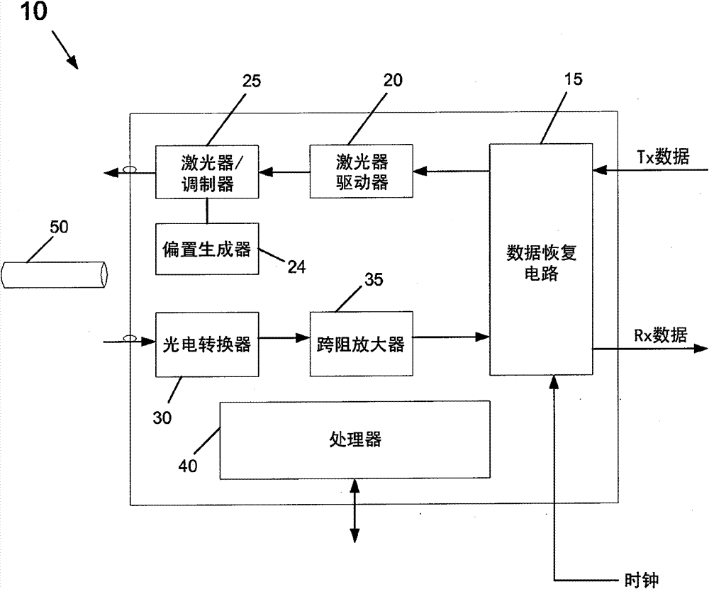
[0011] now refer to figure 1 , which shows a block diagram of an optical transceiver according to an embodiment of the present invention. The transceiver 10 may serve as an interface between the physical layer and the data link layer in a data communication system. Such as figure 1 As shown, transceiver 10 may be used to receive optical information from optical fiber 50 and to transmit optical information to optical fiber 50 . The received data can in turn be converted into electrical energy and provided as received information (RX data) to other parts of the system via the system interface. Similarly, input electrical energy corresponding to data to be transmitted (TX data) may be received from the system and converted into optical energy for transmission via optical fiber 50 .

[0012] Therefore, if figure 1 As shown, the transceiver 10 includes a clock and data recovery circuit (CDR) 15 in the transmit direction, and the data recovery circuit receives data along with a ...


PUM


Abstract

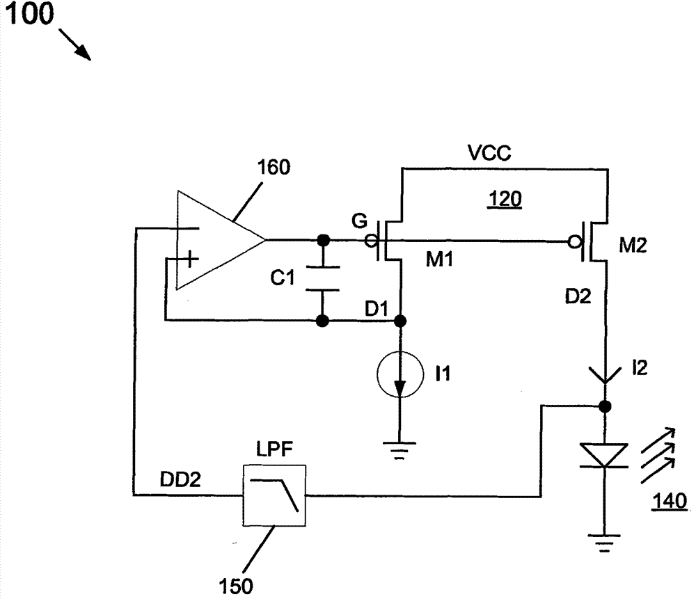
In one embodiment, the present invention includes an apparatus having a current mirror with a current source coupled to a first terminal and an output current to flow from an output terminal, a laser coupled to the output terminal to be biased by the output current, and a comparator to compare a voltage of the first terminal to the voltage of the output terminal and gate the current mirror based on the comparison. Other embodiments are described and claimed.

Description

Background technique [0001] Lasers are used in a wide variety of applications, especially in optical communication systems in which modulated light beams carrying large amounts of information are transmitted over long distances through optical fibers at the speed of light. [0002] Many systems include so-called vertical cavity surface emitting lasers (VCSELs). As the name suggests, this type of laser is a semiconductor microlaser diode that emits a coherent beam normal to the surface of the wafer being fabricated. VCSEL is compact, its mass production cost is relatively low, and it can have advantages compared with edge emitting laser (edge ​​emitting laser). Lasers such as VCSELs are widely used in optical transceivers. Typically, the laser has a direct current (DC) bias current, which keeps the laser on, so that no power up process is required when optical data is to be transmitted, enabling high speed communication. Therefore, when the laser is used for fast switching a...

Claims


Application Information

Patent Timeline
Patent Type & Authority Patents(China)
IPC IPC(8): H01S5/06
CPCH01S5/042H01S5/06808H01S5/06
Inventor M·高D·克鲁斯C·陆
Owner INTEL CORP
Learn More