Current source

a current source and current current technology, applied in the field of current sources, can solve the problems of limiting the minimum operating voltage, increasing the value of output current iout with the supply voltage vdd, and not being able to use a cascoded ptat current generator, so as to reduce the change in output current

Inactive Publication Date: 2005-08-09
STMICROELECTRONICS LTD
View PDF12 Cites 14 Cited by
  • Summary
  • Abstract
  • Description
  • Claims
  • Application Information

AI Technical Summary

Benefits of technology

[0005]According to one aspect of the present invention there is provided a current source adapted to produce an output current comprising: first and second circuit branches connected between first and second reference voltages, the first branch including a branch resistor connected at a junction node to a compensation...

Problems solved by technology

Hence the output current Iout is proportional to the thermal voltage VT, which is proportional to absolute temperature T. One drawback of the circuit of FIG. 1 is that the value of the output current Iout increases with the supply voltage Vdd because of the early eff...

Method used


Image

  • Current source
  • Current source
  • Current source

Examples


Embodiment Construction

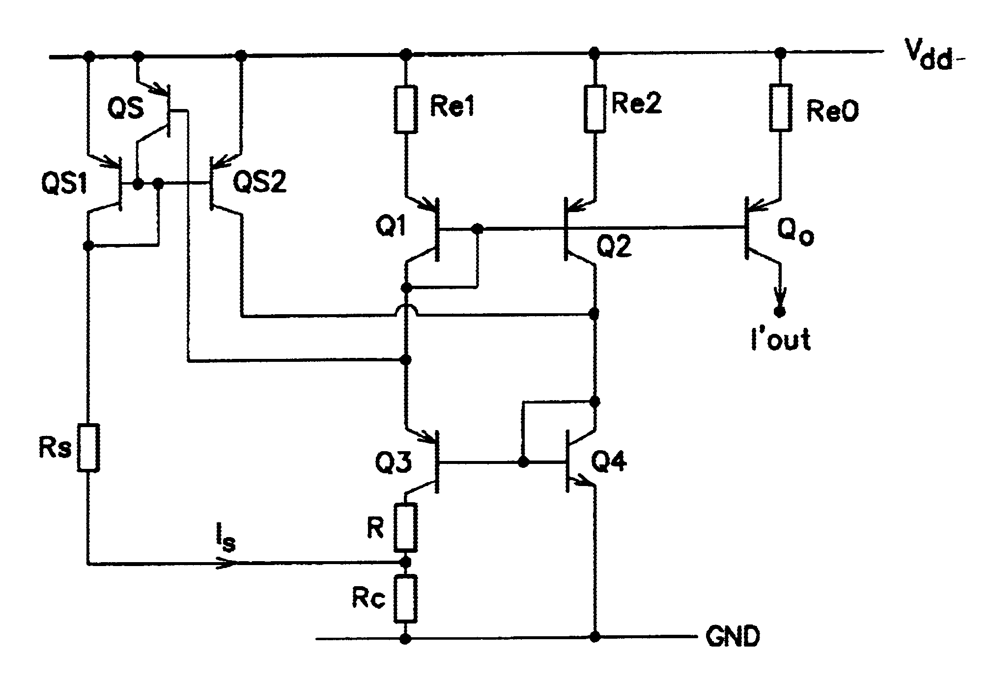
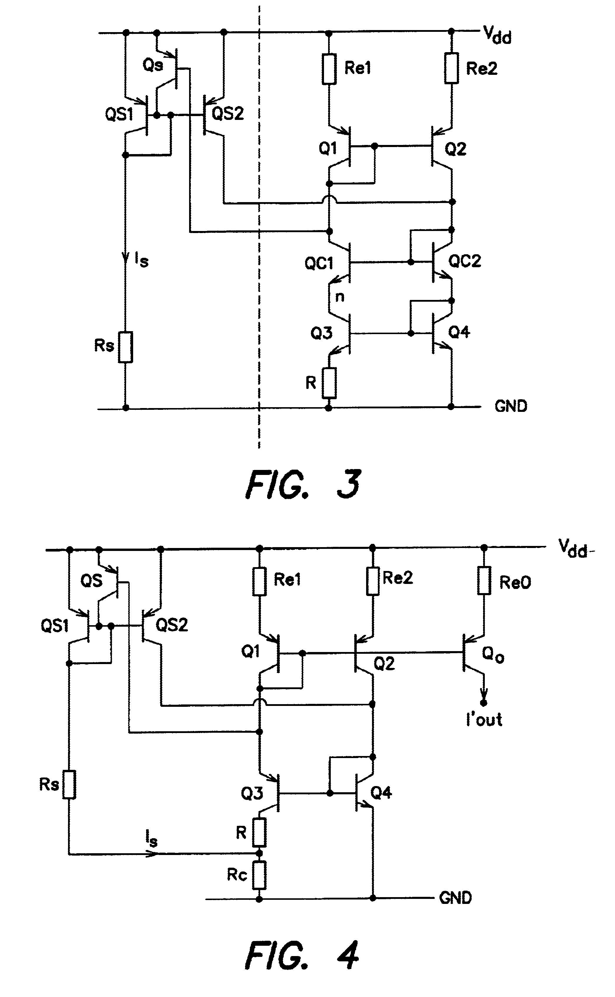
[0013]FIG. 3 illustrates a cascoded current source circuit with start-up circuitry. The current source circuit itself is as illustrated in FIG. 2 and described above. In addition, FIG. 3 illustrates start-up circuitry in the form of mirrored bipolar transistors QS1 and QS2 and a switch transistor Qs. The mirror transistor QS1 has its emitter connected to the upper supply rail Vdd, and its collector connected through a start-up resistor Rs to ground GND and also to its base. The base of the first mirror transistor QS1 is connected to the base of the second mirror transistor QS2 which has its emitter connected to the upper supply rail Vdd and its collector connected to the collector of the transistor Q2 in the second branch of the current source. The switch transistor Qs has its emitter connected to the upper supply rail Vdd, its collector connected to the tied bases of the mirror transistors QS1, QS2 and its own base connected to the collector of the transistor Q1 in the first branch...


PUM


Abstract

A current source, adapted to generate a current proportional to absolute temperature has a greatly reduced supply voltage dependence and is still able to operate at low operating voltages. This is achieved by the incorporation of a compensation resistor through which a start-up current is passed.

Description

FIELD OF THE INVENTION[0001]The present invention relates to a current source, and particularly, but not exclusively, to a current source adapted to generate a current proportional to absolute temperature (PTAT).DISCUSSION OF THE RELATED ART[0002]PTAT current sources are used widely as biased current generators in integrated circuits. A simple implementation of such a source is shown in FIG. 1. The circuit in FIG. 1 has first and second branches connected between supply Vdd and ground GND rails. The first branch comprises a resistor Re1, a first bipolar transistor Q1 with its base tied to its collector, a second bipolar transistor Q3 and a resistor R. The second branch includes a third resistor Re2, a third bipolar transistor Q2 with its base connected to the base of the bipolar transistor in the first branch, and a fourth bipolar transistor Q4 with its base connected to its collector and its base connected to its corresponding bipolar transistor in the first branch. Thus, the first...

Claims


Application Information

Patent Timeline
IPC IPC(8): G05F3/26G05F3/08
CPCG05F3/265
Inventor RASHID, TAHIRDARZY, SAUL
Owner STMICROELECTRONICS LTD
Why Eureka
Try Eureka