Optical mouse with uniform light projection

a mouse and light projection technology, applied in the field of optical mouse, can solve the problems of dust entering the mouse, the operator is not allowed to completely move the mouse, and the mouse is unable to be detected and transmitted light, etc., to achieve the effect of excellent light transmission, simplified assembly, and excellent light transmission

Inactive Publication Date: 2005-08-09
EPISTAR CORP
View PDF8 Cites 13 Cited by
  • Summary
  • Abstract
  • Description
  • Claims
  • Application Information

AI Technical Summary

Benefits of technology

[0006]Therefore, a primary object of the present invention is to provide an optical mouse which projects a uniform light beam for detection of movement of the mouse and an excellent transmission of light can be obtained.
[0008]A further object of the present invention is to provide an optical mouse having excellent result of detection and transmission of light in the mouse.
[0009]To achieve the above objects, in accordance with the present invention, there is provided an optical mouse comprising a bottom casing, a top cover mounted to the bottom casing to define an interior space therebetween, a circuit board and a lens set arranged in the interior space. The bottom casing defines an opening. A detecting device is mounted to the circuit board. A receiving portion and a light emitting diode (LED) are mounted to a bottom side of the detecting device in alignment with a slot defined in the circuit board. A solder pad to which an electrical conductor is connected forms a central bore and is positioned on a circumferential margin of a light projection surface of the LED to allow light projected from the light projection surface to transmit through the central bore. The lens set is arranged between the circuit board and the bottom casing, comprising a reflection member located below the LED for redirecting the light from the LED to the fixture surface and a lens, which is located below the receiving portion of the detecting device and in alignment with the opening of the bottom casing, converging the reflected light toward the receiving portion of the detecting device. Since the light from the LED is allowed to pass through the central bore of the solder pad and is not substantially blocked by the solder pad, a uniform projection of light can be accomplished. The assembly of the optical mouse is simplified and an excellent transmission of light can be realized.

Problems solved by technology

In addition, the cable that connects the mouse to the host computer imposes limitation to the movement of the mouse on the fixture surface.
Thus, an operator is not allowed to completely freely move the mouse to obtain the best operability thereof.
Further, dusts may get into the mouse by the rotation of the track ball.
This may induce poor engagement between components of the mouse in generating and transmission of the signal indicating the movement of the mouse.
The conventional optical mouse, however, suffers non-uniform projection of light from the illuminating element, which is generally an LED.
Such a non-uniform light beam, after being reflected by the fixture surface, induces a poor detection signal on the sensor.

Method used


Image

  • Optical mouse with uniform light projection
  • Optical mouse with uniform light projection
  • Optical mouse with uniform light projection

Examples


Embodiment Construction

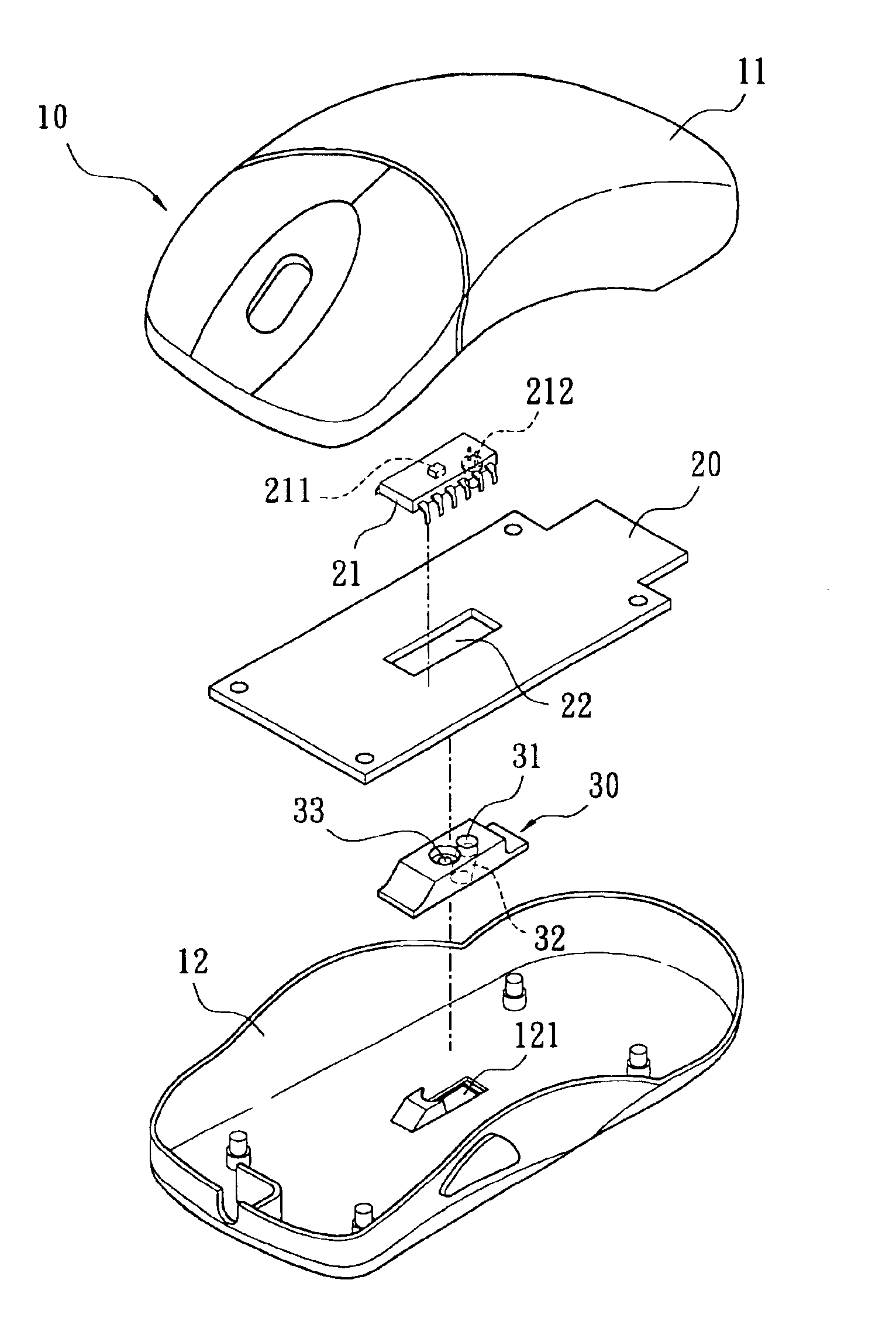
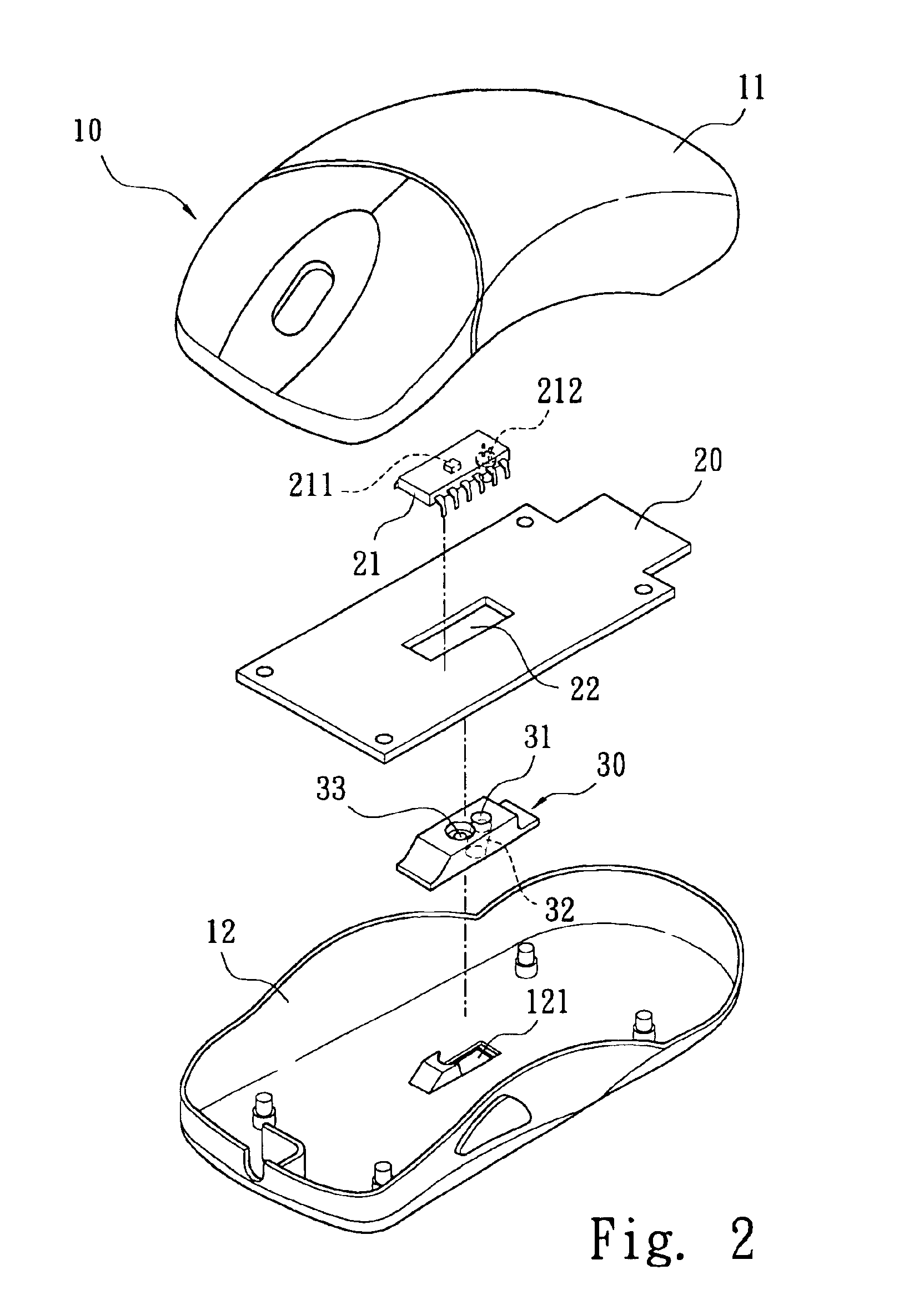
[0017]With reference to the drawings and in particular to FIGS. 1-4, an optical mouse constructed in accordance with the present invention comprises a housing 10 comprising a bottom casing 12 to which a top cover 11 is mounted, defining an interior space therebetween for accommodating a circuit board 20 and a lens set 30. The bottom casing 12 defines an opening 121.

[0018]The circuit board 20 is fixed in the bottom casing 12 and defines a slot 22 substantially aligned with the opening 121 of the bottom casing 12. A detecting device 21 is mounted on the circuit board 20 at a location substantially aligned with the slot 22. On a bottom side of the detecting device 21, a receiving portion 211 of the detecting device 21 and an illuminating device 212 are mounted whereby the receiving portion 211 is substantially aligned with the opening 121 of the bottom casing 12.

[0019]The illuminating device 212, which is a light emitting diode device in the embodiment illustrated, comprises a chip 213...


PUM


Abstract

An optical mouse includes a bottom casing, a top cover mounted to the bottom casing to define an interior space. A circuit board and a lens set are located in the interior space. The bottom casing has an opening. A detecting device is mounted to the circuit board. A receiving portion and a light emitting diode (LED) are mounted to a bottom side of the detecting device in alignment with a slot in the circuit board. A solder pad to which an electrical conductor is connected has a central bore and is positioned on a circumferential margin of a light projection surface of the LED to allow light projected from the light projection surface to transmit through the central bore. The lens set is located between the circuit board and the bottom casing, and includes a reflection member and a lens.

Description

FIELD OF THE INVENTION[0001]The present invention generally relates to an optic mouse, and in particular to an optical mouse that uniformly projects light to be reflected and detected by a sensor whereby assembly thereof is simplified and transmission of light is enhanced. The present invention is suitable for all kinds of optical mouse and similar devices.BACKGROUND OF THE INVENTION[0002]Conventionally, a computer mouse comprises a bottom casing and a top cover mounted to the bottom casing, defining an interior space therebetween for accommodating a circuit board. The circuit board is fixed to the bottom casing and comprises a tracking module substantially aligned with an opening defined in the bottom casing. The tracking module comprises a track ball rotatably mounted inside the mouse and partially projects beyond the bottom casing for engaging a fixture surface on which the mouse is moved. The track ball is rotated when the mouse moves on the fixture surface. The rotation of the ...

Claims


Application Information

Patent Timeline
Patent Type & Authority Patents(United States)
IPC IPC(8): G09G5/08G06F3/03G06F3/033
CPCG06F3/0317G06F3/03543
Inventor CHANG, WEIHUNG, HSIEN-YEH
Owner EPISTAR CORP
Why Eureka
Try Eureka