Diffractive optical element, and optical system and optical apparatus provided with the same

Inactive Publication Date: 2005-08-09
CANON KK
View PDF9 Cites 46 Cited by
  • Summary
  • Abstract
  • Description
  • Claims
  • Application Information

AI Technical Summary

Benefits of technology

[0013]It is an object of the present invention to present a diffractive optical element having a blazed-binary gra

Problems solved by technology

Moreover, it has been reported that for these functions, there are only

Method used


Image

  • Diffractive optical element, and optical system and optical apparatus provided with the same
  • Diffractive optical element, and optical system and optical apparatus provided with the same
  • Diffractive optical element, and optical system and optical apparatus provided with the same

Examples


embodiment 1

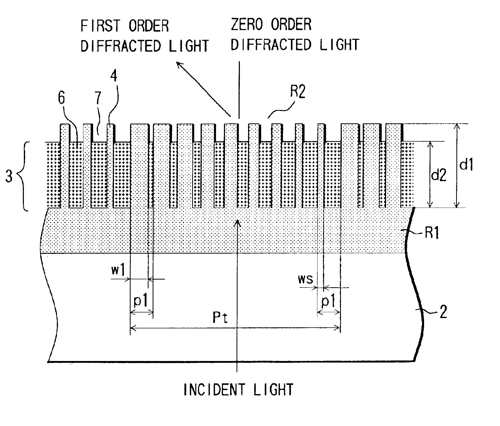
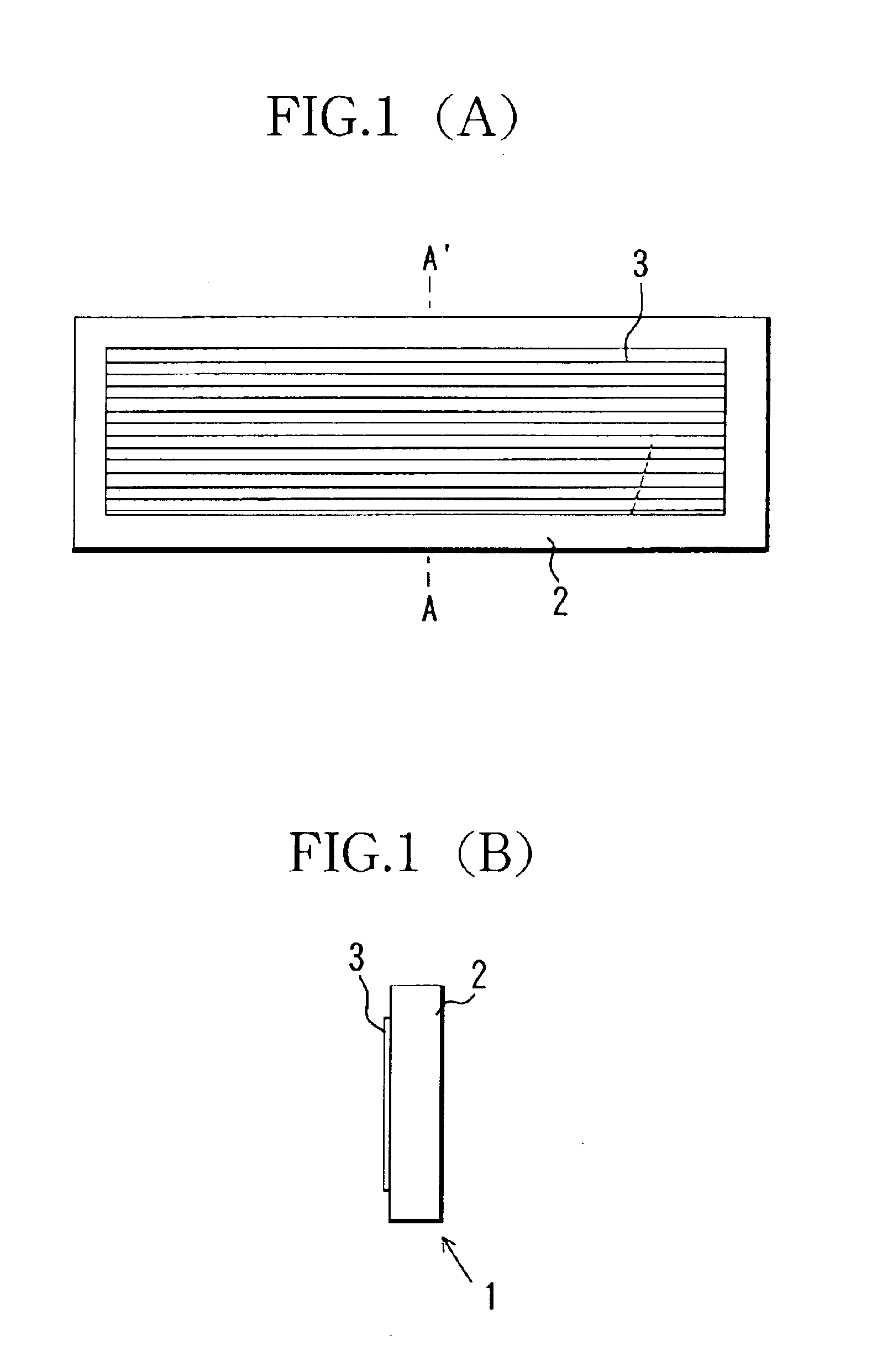
[0031]FIGS. 1(A), 1(B) and 2 show the structure of a diffractive optical element according to Embodiment 1 of the present invention. The diffractive optical element 1 is configured by providing a transparent blazed-binary diffraction grating 3 on a transparent substrate 2.

[0032]The blazed-binary diffraction grating 3 has a periodic structure in which one-dimensional comb-tooth-shaped grating units are formed in repetition, and with respect to the direction A-A′ in FIG. 1(A), it has a grating unit period Pt, which is larger than the wavelength of the incident (used) light (used wavelength). Moreover, light that is incident on the diffractive optical element is diffracted only in a specific direction, which depends on the grating unit period Pt and the design order m.

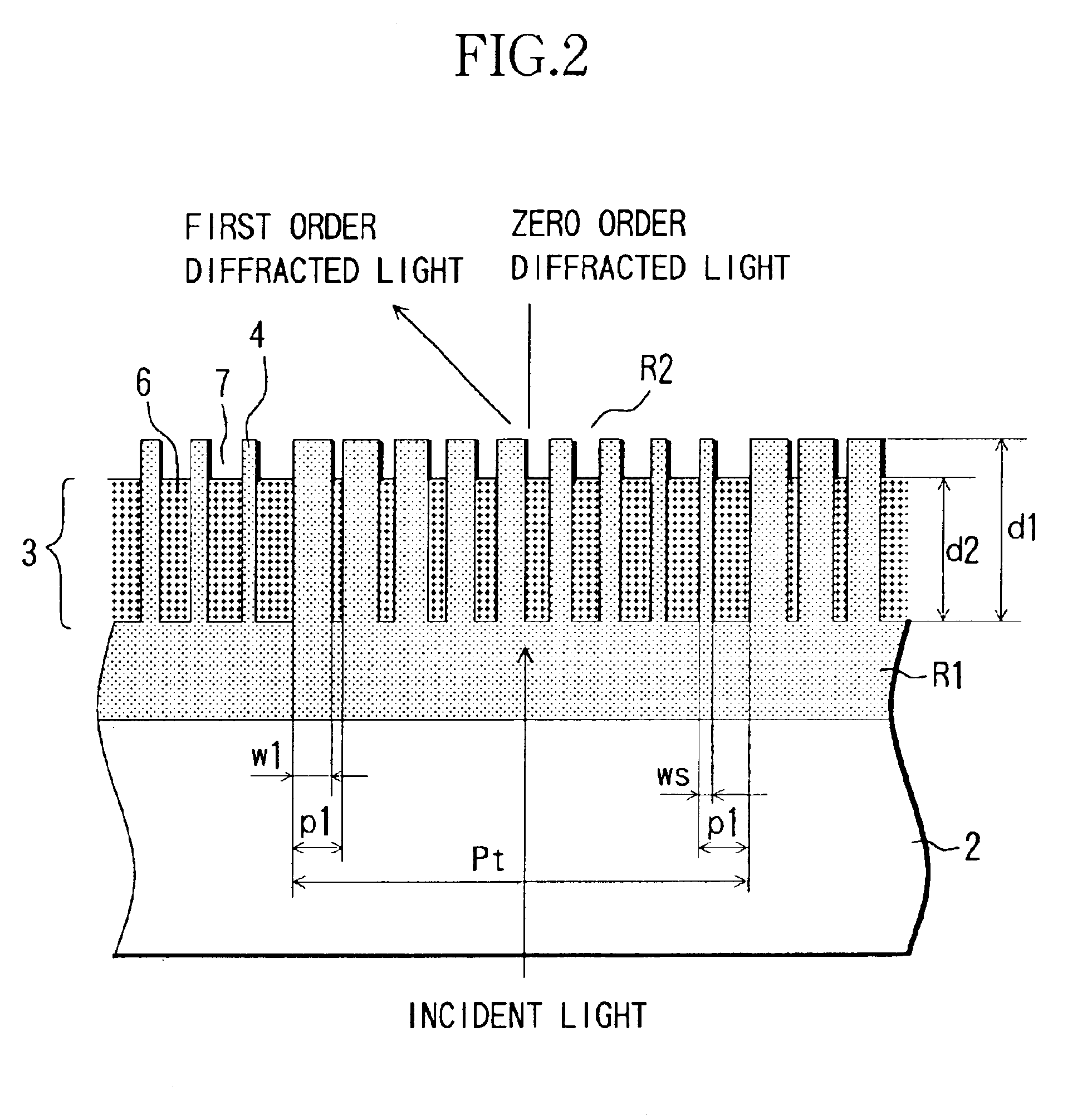
[0033]In FIG. 2, the blazed-binary diffraction grating 3 that is provided on the substrate 2 is configured to have a plurality of first grating portions 4 that are made of a first material having a refractive index that i...

embodiment 2

[0070]FIG. 4 shows the structure of a diffractive optical element according to Embodiment 2 of the present invention. The diffractive optical element 1′ of this embodiment is different from Embodiment 1 in that the blazed-binary diffraction grating 3 is formed in contact with the substrate 2. For this reason, the bottom surface 8 of the grating grooves is the substrate surface. It should be noted that in this embodiment, structural elements that are the same as in Embodiment 1 have been denoted by the same numerals as in Embodiment 1.

[0071]With this structure, when the first grating portions 4 are fabricated for example by etching with a material other than a resin, the substrate 2 can serve as an etching stopper layer, and the grating height can be controlled with high precision.

[0072]Furthermore, it becomes possible to select the refractive index of the material of the substrate 2 so as to minimize the reflection loss occurring at the border 9 between the grating bottom surface an...

embodiment 3

[0073]FIG. 5 shows the structure of a diffractive optical element according to Embodiment 3 of the present invention. FIG. 5(A) is a cross-sectional view of the diffractive optical element, and FIG. 5(B) is a plan view of the diffractive optical element. It should be noted that in this embodiment, structural elements that are the same as in Embodiment 1 have been denoted by the same numerals as in Embodiment 1.

[0074]In addition to the structure explained in Embodiment 1, the diffractive optical element 1″ of this embodiment has a periodic structure, in which the second and the third material are arranged alternately with regard to the direction perpendicular to the period of the blazed-binary diffraction grating 3. Then, by making the repetition period smaller than the used wavelength it is possible to provide the properties of a SWS diffractive optical element.

[0075]Moreover, with this structure, setting the height of the first and second gratings 4 and 6 uniformly to d1, the same ...


PUM


Abstract

A diffractive optical element of the blazed-binary grating type is disclosed, with which a high diffraction efficiency can be achieved over substantially the entire used wavelength region. The diffractive optical element has a periodic structure taking a grating unit including a plurality of grating portions with different grating width and grating interval as one period. The diffraction element further includes a plurality of first grating portions made of a first material and a plurality of second grating portions made of a second material having a different refractive index than the first material that are arranged between the first grating portion.

Description

BACKGROUND OF THE INVENTION[0001]1. Field of the Invention[0002]The present invention relates to diffractive optical elements, and more particularly to diffractive optical elements having a blazed-binary grating, as well as optical systems and optical apparatuses provided with the same.[0003]2. Description of the Related Art[0004]Conventional diffractive optical elements serving as diffraction lenses with the purpose of reducing chromatic aberration are disclosed in SPIE Vol. 1354 International Lens Design Conference (1990), for example.[0005]Color separation gratings utilizing the fact that the diffraction angle differs depending on the wavelength of the incident light in order to perform color separation are disclosed for example in Japanese Patent Publication No. 1993-46139 (corresponding to U.S. Pat. No. 5,113,067). Furthermore, recently, a diffractive optical element known as SWS (sub-wavelength structure) grating, whose grating period has a microscopic periodic structure that ...

Claims


Application Information

Patent Timeline
IPC IPC(8): G02B5/18
CPCG02B5/1876
Inventor NAKAI, TAKEHIKO
Owner CANON KK
Why Eureka
Try Eureka