Laser device and lens position adjustment method in the laser device

Inactive Publication Date: 2005-08-09
CANON KK
View PDF14 Cites 41 Cited by
  • Summary
  • Abstract
  • Description
  • Claims
  • Application Information

AI Technical Summary

Benefits of technology

[0011]The present invention has been made in view of the above and other drawbacks, and it is therefore an object of the present invention to provide a laser device, a laser scanning device and an ima

Problems solved by technology

However, in the case of the above-mentioned conventional art, there are problems as described below.
In addition, costs are increased in comparison with a lens manufactured by machining because a molded product is used.
Hei 9-218368 (see FIG. 22) rigidity of a lens holding member tends to decrease and th

Method used


Image

  • Laser device and lens position adjustment method in the laser device
  • Laser device and lens position adjustment method in the laser device
  • Laser device and lens position adjustment method in the laser device

Examples


Example

[0041]Preferred embodiments of the present invention will be hereinafter described illustratively in detail with reference to drawings. However, dimensions, materials and shapes of components described in the embodiments and relative arrangements thereof are not construed to limit the scope of the present invention only to them.

[0042]FIG. 13 is a schematic view of an image forming apparatus to which the present invention is applied.

[0043]In FIG. 13, reference numeral 50 denotes a laser scanning device, 51 denotes a photosensitive drum, 52 denotes charging means, 53 denotes developing means, 54 denotes transferring means, 55 denotes fixing means, 56 denotes cleaning means and 57 denotes a mirror.

[0044]The photosensitive drum 51 charged by the charging means 52 is scanned by a laser beam irradiated from the laser scanning device 50 via the mirror 57 and an electrostatic latent image is formed on the photosensitive drum. The electrostatic latent image on the photosensitive drum 51 is d...


PUM


Abstract

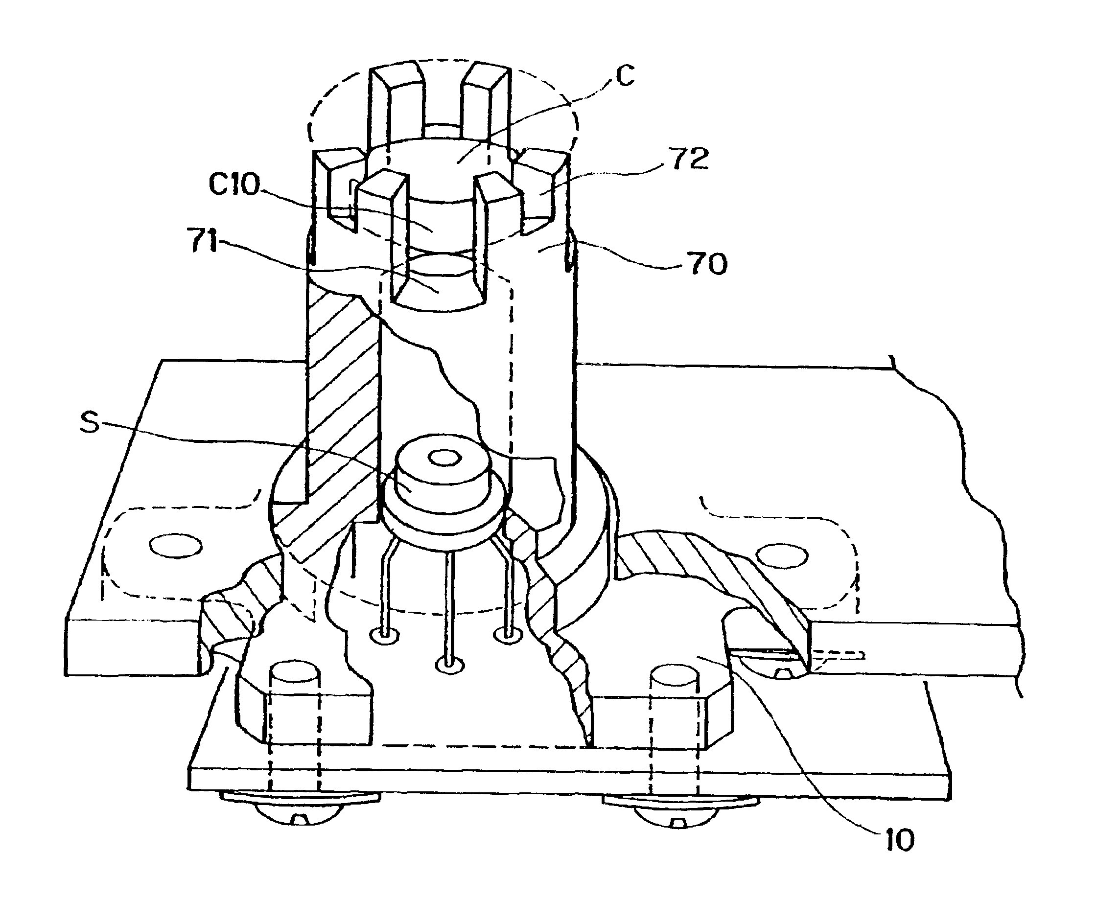
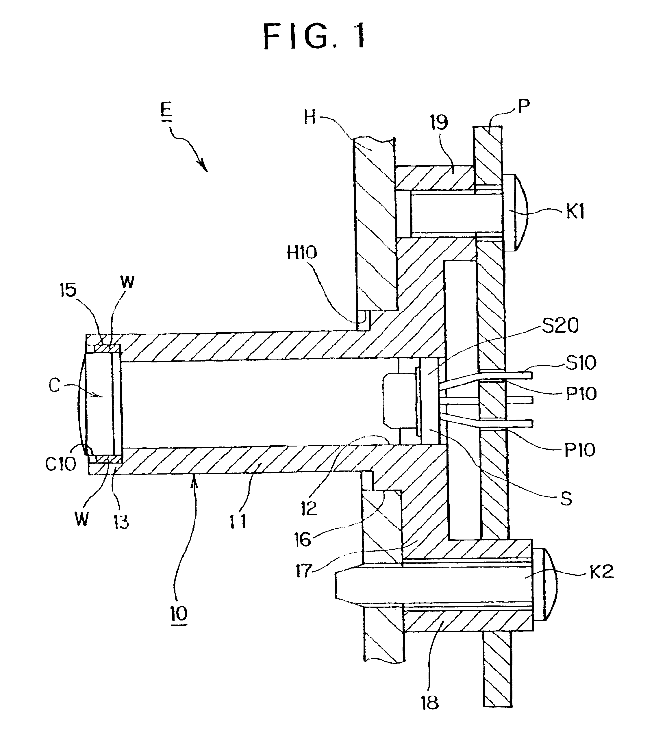
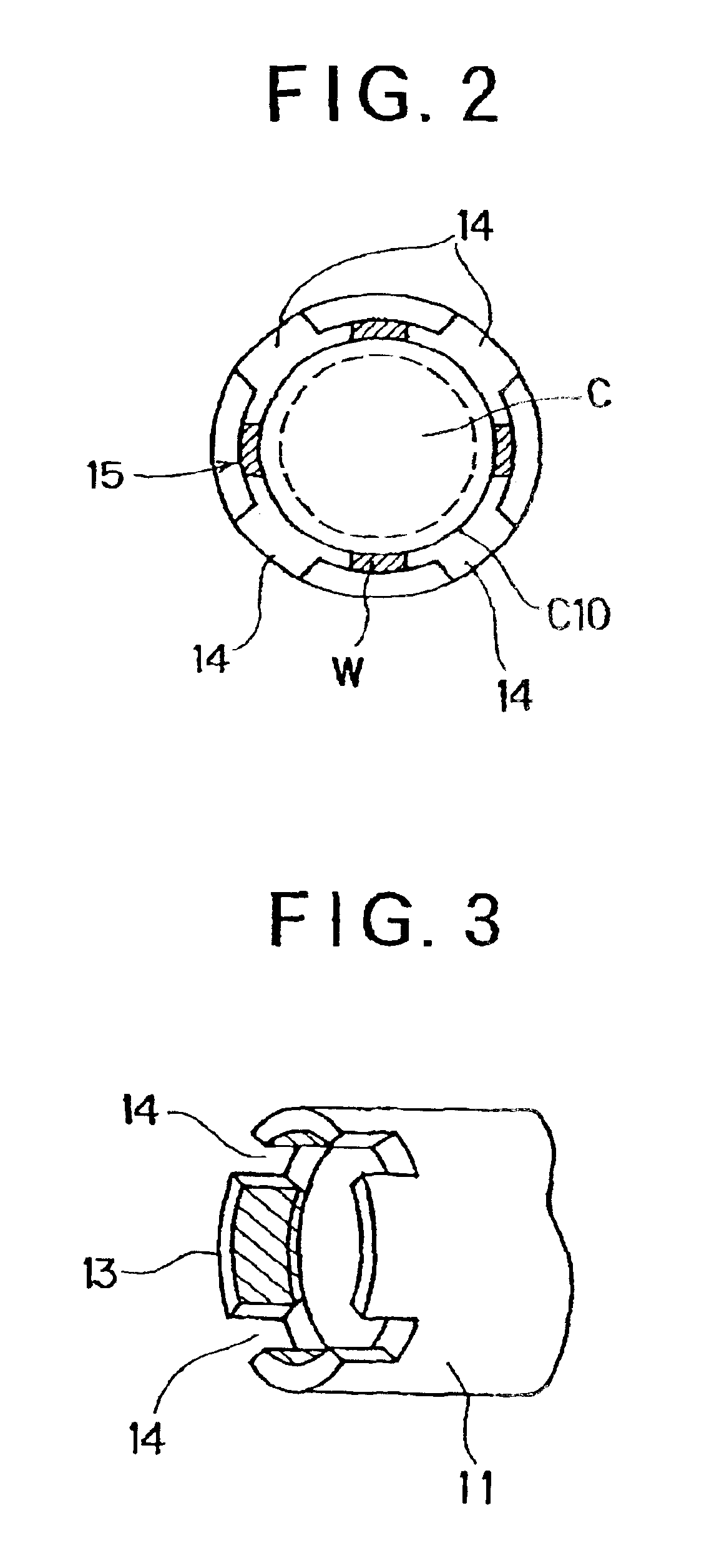
A recess 14 is provided in a lens accommodating portion 13 of a laser holder 10 for holding a collimator lens C, whereby positional accuracy and adhesion strength of the lens and a light source are improved.

Description

BACKGROUND OF THE INVENTION[0001]1. Field of the Invention[0002]The present invention relates to a laser device to be applied to an image forming apparatus such as a laser beam printer, a laser facsimile and a copying machine and, more specifically, to a position adjustment of a lens in the laser device.[0003]2. Description of the Related Art[0004]Conventionally, as a form of a light source device composed of a light source using a semiconductor laser of this type and a collimator lens for focusing a laser beam in a predetermined spot shape, there is, for example, a conventional device using an optical element in which a collimator lens portion and a lens holder portion are integrally formed with a part of the optical element being fixed by an adhesive to a holding member of the semiconductor laser.[0005]In addition, Japanese Patent Application Laid-open No. Hei 8-112940 discloses a light source device in which a collimator lens C is held on a lens holder 400 by a method such as adh...

Claims


Application Information

Patent Timeline
IPC IPC(8): G02B7/02B41J2/44G02B26/10H01S5/022
CPCG02B7/025
Inventor SATO, WATARUKOBAYASHI, HISANORI
Owner CANON KK
Why Eureka
Try Eureka