Image measurement and display device, image measurement and display system, construction management method, and construction status monitor system

a technology of image measurement and display device, which is applied in the direction of image enhancement, instruments, and using wave/particle radiation means, etc., can solve the problems of difficult placement of finishing stakes, difficult to actually carry out construction exactly as indicated, and often takes a long time for operators to complete placement work

Inactive Publication Date: 2005-08-09
KK TOPCON
View PDF12 Cites 30 Cited by
  • Summary
  • Abstract
  • Description
  • Claims
  • Application Information

AI Technical Summary

Benefits of technology

[0010]The first object of the invention is to provide an image measurement and display device capable of measuring in detail objects to be constructed or manufactured and comparing accurately the measurements with design drawings. The second object is to provide such an image measurement and display device that enables a person in charge of construction or manufacturing to find out easily whether or not the construction or manufacturing is carried out in compliance with design drawings and enables the person to carry out the construction or manufacturing exactly as specified on the design drawings in a simple manner. The third object is to provide a construction status monitor system useful for finding out accurately the daily status of progress in construction or manufacturing and for organizing the construction or manufacturing flexibly to meet construction plans.
[0012]In such an arrangement, the status of the construction on the construction site is remotely measured by measuring in the shape measuring section 350 the shape data of the object from the paired stereovision images of the object taken with the image taking section 220. In the memory section 340 are stored target data related to the object image, which target data are to be the completion target of the construction site. The image display section 330, 110a is placed, for example, in the vicinity of the construction management person distant from the work machine or in the operation cabin of the work machine to display the paired stereovision images of the object superposed over the stereovision target data images of the object based on the target data. The comparison display processing section 360, 120a compares the shape data of the object with the target data, and reflects the comparison results on the superposed display on the image display section 330, 110a, so that the construction operator or the construction management person can easily find out the relationship between the current status on the construction site and the target data by means of the superposed display of the comparison results.
[0014]In such an arrangement, the imaging position of the image taking section 220 is measured with the imaging position measuring sections (250, 252). Therefore, the information on the imaging position measured with the imaging position measuring sections (250, 252) may be used in mutual comparison and superposition of the object shape and the shape corresponding to the target data in the image display sections 330 and 110a and the comparison display processing section 360, 120a, so that the image conversion processing required for the superposition is carried out smoothly.
[0015]In the first and second inventions, it is preferable that the comparison results obtained with the comparison display processing section 360, 120a are reflected by the display on the image display section 330, 110a so that the part where the shape of the object approximately agrees with the shape corresponding to the target data is displayed distinguishably, so that the status of the construction based on whether or not the target data are reached is easily found out. The first and second inventions are preferably constituted that, as the results of the comparison with the comparison display processing section 360, 120a, the distance or interval to the object is associated with that to the target data, and then their comparative sized of the object and the target data are displayed distinguishably on the image display section 330, 110a, so that whether or not the construction status has reached the target data is easily found out by using the comparative sizes of the object and the target data. In the first and second inventions, it is preferable to provide an intermediate target data setting means 370 for setting intermediate target data as the target data for the comparison display processing sections 360, 120a and the image display sections 330, 110a, in every stage of construction on the object and also preferable to constitute the comparison display processing section 360, 120a so as to compare the object shape with the shape corresponding to the intermediate target data, so that intermediate target data exactly matching the daily status of construction are displayed in such a manner that can be understood by the person in charge of the construction and the person who manages the construction.
[0019]In the above device, the imaging position of the image taking section 220 is measured with the imaging position measuring sections (250, 252). Therefore, the information on the imaging position measured with the imaging position measuring sections (250, 252) may be used in comparing and superposing the object shape with the shape corresponding to the target data by means of the image observing section 110 and the comparative observation display processing section 120, so that image conversion processing required for superposing the stereovision target data image display over the real image of the object is carried out smoothly.
[0020]In the third and fourth inventions, it is preferable that the image observing section 110 includes at least one of a head-up display and a head-mount display, so that the person in charge of the work can see the stereovision target data image while seeing the object by the naked eye without moving the line of sight. In the third and fourth inventions, it is preferable that the results of the comparison carried out with the image processing section 120 for forming the image to carry out comparative observation and display are reflected on the display of the image observing section 110, so that positions may be discriminated where the object shape is found to match approximately the shape corresponding to the target data, and that the status of the construction is easily found out on the basis of whether or not the target data are reached. In the third and fourth inventions, it is preferable that the comparative result in the image processing section 120 forming images for performing comparative observation display is the distance or interval to the object and the target data and that the comparative sizes of the object and the target data are displayed on the image observing section 110 so that whether or not the construction status has reached the target data is easily found out by using the relative sizes of the object and the target data.

Problems solved by technology

However, with the above methods of controlling the construction status, the construction is difficult for the operator to carry out actually exactly as indicated on the design drawings.
(1) The method with finishing stakes can make only rough comparison with the design drawings. Moreover, the ground is steep in some places and it is difficult to place the finishing stakes. Because the finishing stakes must be placed by the operator, the placement work often takes much time in particular on a natural ground.
(2) Since the method using laser is intended to control horizontal positions, the work on a sloping ground or face of slope requires auxiliary equipment. The problem of difficulty in placing the auxiliary equipment on the steep natural ground remains the same with the method using finishing stakes.
(3) The method of taking the image of the construction status with a remote control camera and comparing the taken image with the design drawings has a problem that the superposition of the design drawing, namely CG (computer graphics) image, on the real image is difficult, and that the design drawing is absorbed in the real image and is not easy to seen. Still another problem for the operator is that the visual point of the image taken with the camera is different from the visual point of the operator who is actually operating the work machine, requiring much skill to operate the work machine while holding down the difference between the taken image and the design drawing.
On the other hand, the person who manages the construction has problems of difficulty in finding out daily status of progress of the construction and difficulty in quickly planning future man-hours and construction based on current status.

Method used


Image

  • Image measurement and display device, image measurement and display system, construction management method, and construction status monitor system
  • Image measurement and display device, image measurement and display system, construction management method, and construction status monitor system
  • Image measurement and display device, image measurement and display system, construction management method, and construction status monitor system

Examples


first embodiment

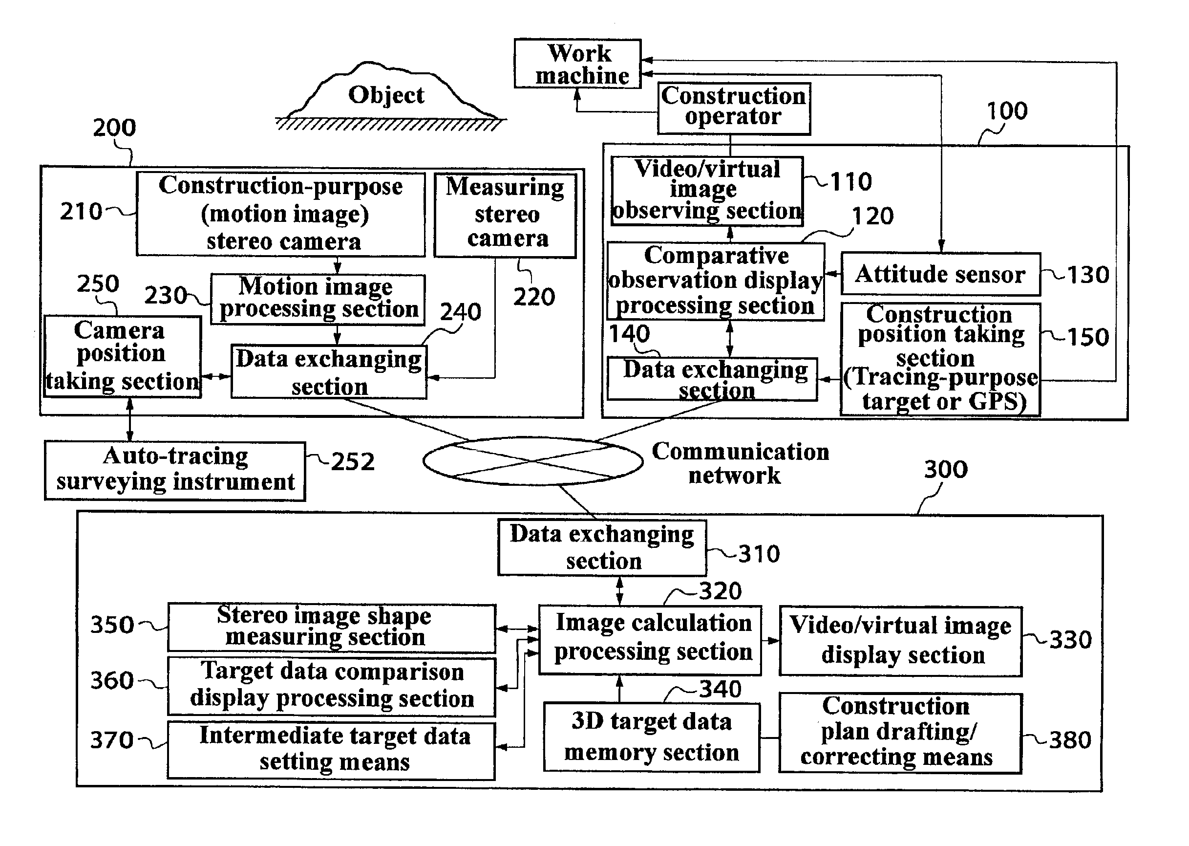
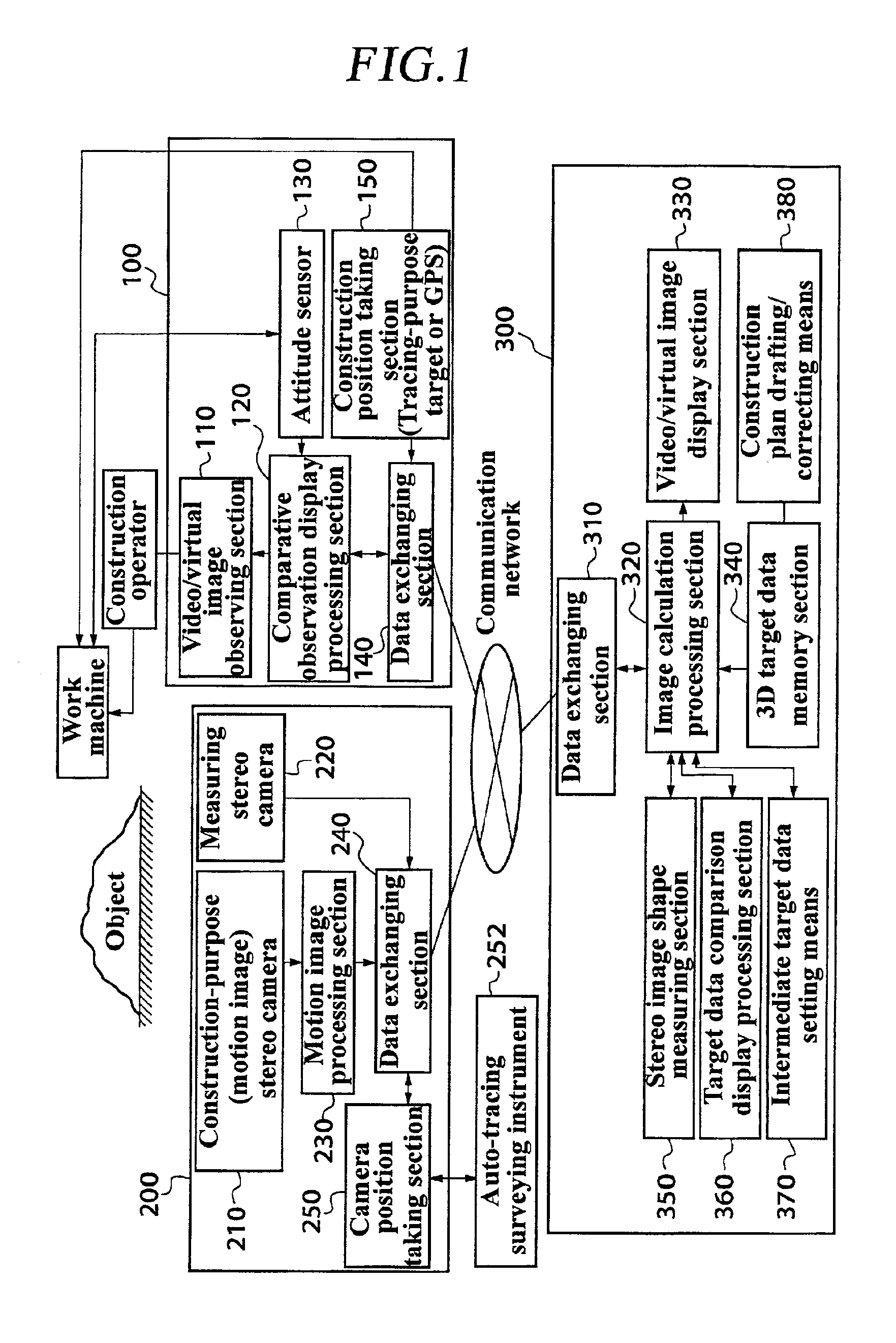
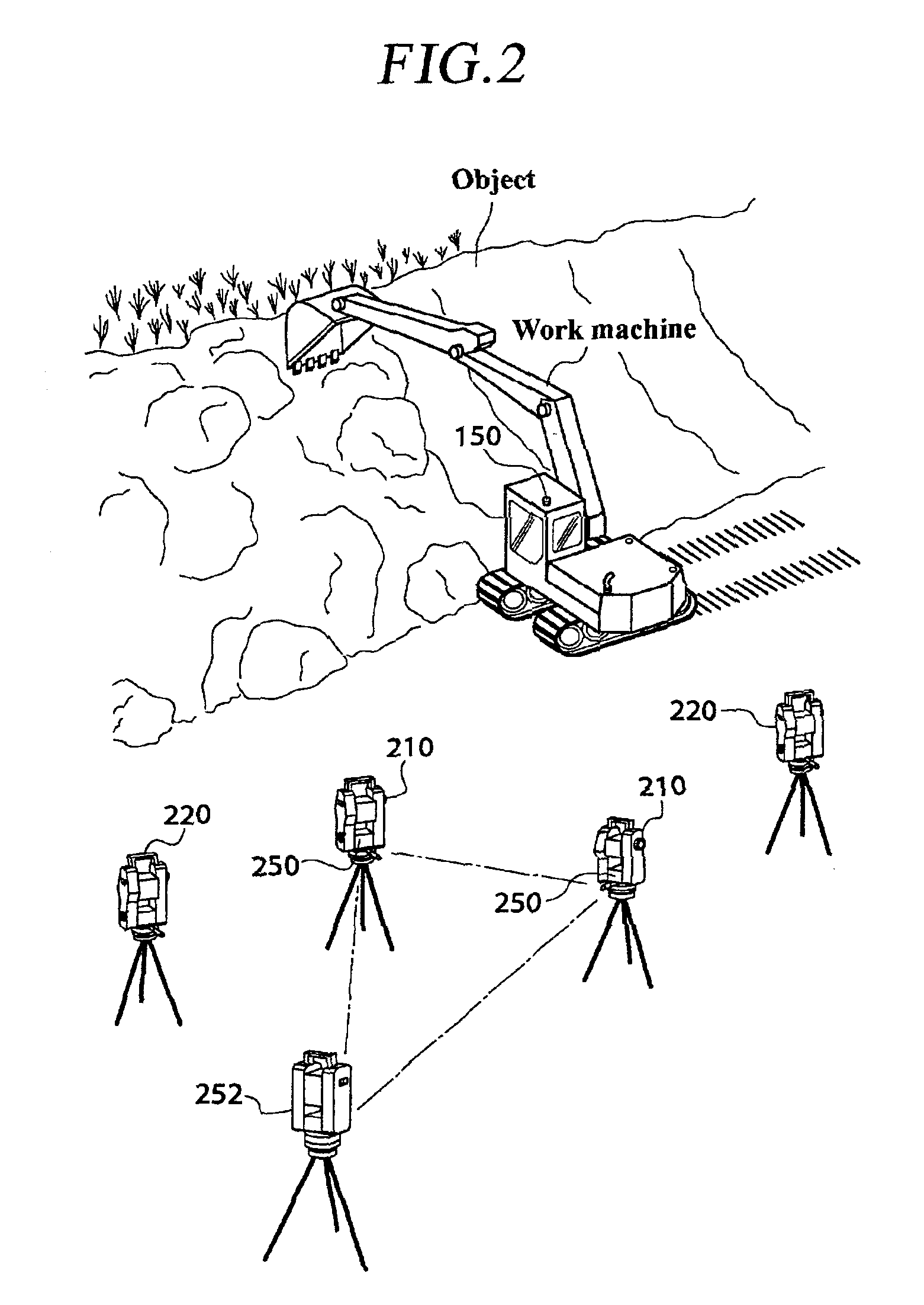
[0064]FIG. 3 is a block diagram, showing use of the construction display device on the construction site. FIG. 2 is a bird's-eye view of the construction display device used on a construction site. The construction display device 100 is attached either to a work machine such as a power shovel executing construction or to a work machine operator. The position of the construction display device 100 is constantly measured in three dimensions with the automatic tracing type of surveying instrument 252 to align the positions of the image of the construction executing visual point, the design image, and the image of the monitoring unit 200. In areas where video waves can be received from orbiting satellites, the GPS may be used in place of the automatic tracing type of surveying instrument 252 as the construction position taking section 150. Unless the construction area is vast, using the automatic tracing type of surveying instrument results in higher accuracy and reliability of the posi...

case 1

[0098] a−b=0 (R82). This condition means that the target data are reached, and a virtual wall is displayed at the reached point in the changed area (R84). That is, the display of the virtual wall shown in FIG. 10 means that the designed position is reached. In the case the reached point is part of the target data, it is preferable to indicate only that part in a different color, indicating that the part need not be processed any more.

case 2

[0099] a>b (R86). This condition means that the target data are exceeded and a warning display is shown (R88). In this case, the area in which the target data are exceeded may be indicated in a different color in two dimensions together with a message display.


PUM


Abstract

A device includes a shape measuring section 350 for measuring shape data from a pair of stereovision images of an object taken with an image taking section 2209 a memory section 340 for storing target data related to the images of the object; an image display section 330 for superposing the paired stereovision images of the object and the stereovision target data image based on the target data and for displaying the images; and a comparison display processing section 360 for comparing the shape data of the object measured by the shape measuring section 350, with the target data and reflecting the results of the comparison on the superposed display on the image display section 330.

Description

BACKGROUND OF INVENTION[0001]1. Field of the Invention[0002]The invention relates to an image measurement and display device, an image measurement and display system, and a construction management method suitable when used in constructing large scale structures such as dams and power stations and in development of residential sites, and particularly to those that enables a person in charge of carrying out the construction or manufacturing to easily find out if the construction or manufacturing is carried exactly as shown on design drawings. The invention also relates to an image measurement and display device, an image measurement and display system, and a construction management method that enable to find out at a construction management office the status of the construction or manufacturing of objects being constructed or manufactured and, particularly to those that enables detailed measurement of objects being constructed or manufactured and enables accurate comparison with desig...

Claims


Application Information

Patent Timeline
Patent Type & Authority Patents(United States)
IPC IPC(8): G06T7/00H04N13/00G01C11/04G06T1/00H04N13/239
CPCG06T7/0075H04N13/0059G01C15/00H04N13/0239H04N13/0221H04N2013/0081G06T2207/10012G06T7/593H04N13/194H04N13/221H04N13/239G01C1/04
Inventor KOCHI, NOBUO
Owner KK TOPCON
Why Eureka
Try Eureka